- 1 Features
- 2 Advantages
- 3 Application
- 4 Inside RITTER MilliGascounter Production (Video EN)
- 5 Measurement Principle with Schematic
- 6 Measuring-Range
- 7 Accuracy
- 8 Performance Data
- 9 Display, Signal Output
- 10 Data Acquisition with PC
- 11 Available Models (Materials)
- 12 Standard Equipment
- 13 Accessories
- 14 Data-sheets
- 15 Downloads
- 16 Manual
RITTER MilliGascounters
Features
Advantages
Application
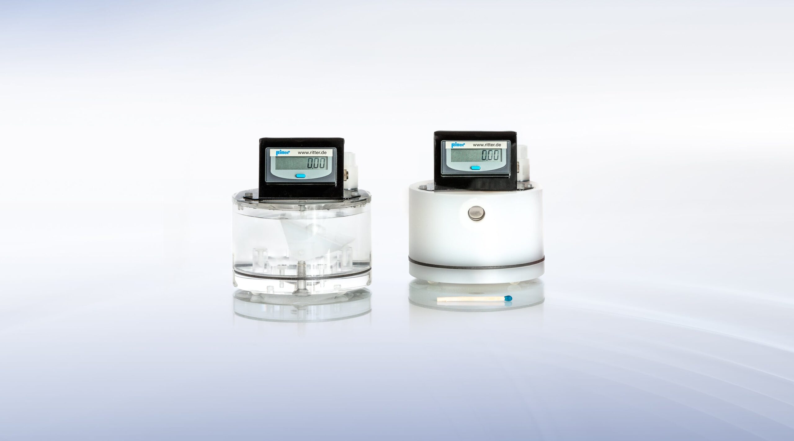
RITTER MilliGascounters (1) (MGC) are designed for the volumetric measurement of the smallest amounts of gas with ultra-low flow rates. They are suitable for measurement of all inert, slightly corrosive gases such as biogas (PMMA model) and aggressive gases (PVDF model). Furthermore, MilliGascounters can be used for volumetric leak detection. (1) Developed at the University of Applied Sciences Hamburg, Prof. Dr. Paul A. SchererInside RITTER MilliGascounter Production (Video EN)
Measurement Principle with Schematic
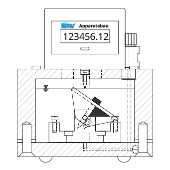
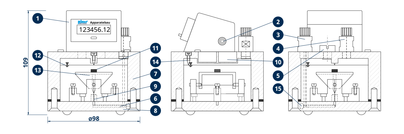
The gas to be measured flows in via the gas inlet nozzle (3), through the micro capillary tube (9) located at the base of the MilliGascounter and up into the liquid casing which is filled with the packing liquid (12). The gas rises as small gas bubbles through the packing liquid, up and into the measurement cell (13). The measurement cell consists of two measuring chambers, which are filled alternatingly by the rising gas bubbles. When a measuring chamber is filled, the buoyancy of the filled chamber causes the measurement cell to tilt abruptly into a position where the second chamber begins to fill and the first chamber empties. The measurement of gas volume therefore occurs in discrete steps by counting the tilts of the measurement cell (13) with a resolution of approximately 3 ml (= content of one measuring chamber). This »residual error« (= max. 3 ml) caused by the resolution should be taken into account when estimating / calculating the total measurement error. The tilting procedure of the measurement cell generates a pulse through the permanent magnet (11) on top of the cell and one of the two magnetic sensors (reed contacts) (10), which is registered by the counter unit (1). For external data logging (PC) the switching pulses of the second reed contact can be obtained via the signal output socket (2). The measured gas exits through the gas outlet nozzle (4).

Legend
- Counter unit with LCD display
- Signal output socket (reed contact)
- Gas inlet
- Gas outlet
- Screw plug for filling
- Gas inlet channel
- Casing
- Base plate
- Micro capillary tube
- Two reed contacts
- Permanent magnet
- Packing liquid
- Measurement cell (tilting body) with twin-chambers
- Tracing screw for liquid level (with MilliGascounter MGC-1 PMMA)
- Inspection screw gas inlet channel
Measuring-Range
The minimum flow rate is theoretically zero ltr/h as there are no mechanical limitations with the MilliGascounter which would define a minimum flow. However, at such micro flow rates there are external influences becoming evident: temperature and pressure variation, tightness of the tube connection, permeability of the gas inlet hose. Therefore, the minimum flow rate was defined as 1 ml/h. The maximum flow rate is 1.0 ltr/h.Accuracy
Because of the physical measurement principle, the measurement error is dependent on the flow rate and it rates ±3 % across the full flow rate range. Each MGC is individually calibrated at the standard flow rate of 0.5 ltr/h so that the measurement error is approx. 0% at this flow rate. At minimum flow rate the measurement error is approximately +3 %, at maximum flow rate approximately -3 %. The »RIGAMO« software (available as accessory) provides an algorithm which automatically recalculates the actual measurement data into the real volume at the respective actual flow rate on the basis of the calibration curve. The remaining error is smaller than ±1% across the full flow rate range.Performance Data
| Minimum flow Qmin | 1 | ml |
| Maximum flow Qmax | 1 | ltr/h |
| Measurement accuracy (1) | ±3 | ±1 | % |
| Measuring drum volume, approx (2) | 3 | ml |
| Min. measuring volume (resolution) (3) | 3 | ml |
| Packing liquid quantity, approx | 120 | ml |
| Diameter | 98 | mm |
| Height | 109 | mm |
| Weight | 475 to 650 | g |
| Maximum gas inlet pressure | 100 | mbar |
| Minimum gas inlet pressure | 8 | mbar |
| Gas inlet pressure at start of measurement (5) | 9 | mbar |
| Gas Temperature (4) | 10 to 60 / 80 | °C |
| Minimum dial division (6) | 0.01 | ml |
| Maximum indication value (6) | 999,999.99 | ml |
| Connection gas in/outlet | Screw-type tube coupling | |
| Outside-Ø | 6 | mm |
| Inside-Ø | 4 | mm |
- (1) Because of the physical measurement principle, the measurement error is dependent on the flow rate. The data acquisition software »RIGAMO« (accessory) provides an algorithm, which automatically recalculates the actual measurement data to the real values at the respective actual flow rate on the basis of the calibration curve. Thus, the remaining error can be reduced significantly or the flow rate range can be extended at the constant measurement error of ±3%. The remaining error is better than approx. ±1% across the full flow rate range.
- (2) = Nominal value; exact value will be determined by individual calibration
- (3) = Volume of measuring chamber
- (4) Max. Operating temperature for PMMA/PVDF. For complete MGC unit applies: With temperatures > room temperature (e.g. if placed in heating furnace) a foam formation of the packing liquid was monitored in particular cases.
- (5) The minimum gas inlet may be increased if the measurement starts with a high flow rate. In this case a higher pressure is needed until the micro capillary in the base plate is clear of packing liquid.
- (6) Because of calibration factor with 2 decimals
Display, Signal Output
The volume of the measured gas is displayed on the electronic digital display located on top of the MGC casing. Additionally a floating reed contact can be used as a signal output.Data Acquisition with PC
For data acquisition of gas volume and flow rate the Windows software »RIGAMO« is available. The data of up to 24 Ritter gas meters can be transmitted to the USB port of a PC.Available Models (Materials)
The MGCs are available in the following casing/measurement cell materials:Standard Equipment
- LCD Display, resettable, 8-digit
- Pulse Generator V6.0 (Reed Contact), as signal output (floating output)
- Twin-chamber measurement cell
- Level
- Gas connection tube (PVC), 1.5 m
- Screw-type tube connection for connection tube (Øi 4 mm, Øo 6 mm)
- Connection gas inlet/outlet (screw-type tube coupling Øi 4 mm, Øo 6 mm)
- Funnel, for filling of liquid
- Packing liquid, 200 ml
- Syringe, for fine adjustment packing liquid level
- Cleaning rod for micro capillary, each per 1 to 5 MGCs
Accessories
- Software »RIGAMO« RIGAMO
- Packing Liquid HCl solution 1.8 vol% for gas mixtures with CO2
(available quantities: 100 / 200 / 500 / 1,000 / 5,000 ml) - Packing Liquid Silox for gas mixtures without CO2
- Filter 0.45 micron for gas inlet tube
- Filter-Check Valve Combination
- Back-pressure valve for gas inlet tube
Data-sheets
- MGC-1 PMMA
- MGC-1 PVDF
- Block-MGC 9x in preparation


