RITTER Bellows-type Gas Meters
Application
RITTER Bellows-type Gas Meters are applicable for measuring the volume of flowing inert and dry gases and are particularly effective at high gas flows. Please note that gases containing aggressive components or water vapour may reduce the life span of bellows-type gas meters, if the casing of the measuring unit (tinplate), the valve/control elements (polyamide) or the bellows (Perbunan®) should be attacked. Further details on the materials that may come into contact with gases can be found under »Materials«.
The desired measurement range can be selected from among 6 magnitudes (types) extending together as a whole from 40 ltr/h to 160 m3/h at a gas temperature ranging from -20 °C to +50 °C. The solidly soldered casing on the standard model is designed to withstand a maximum overpressure of 50 mbar (BG 40/100: 0.5 bar).Advantages
The major advantage and the superiority of volumetric gas meters (like bellows-type gas meters) over other measurement principles, which determine gas volume using secondary measurable variables such as speed, heat capacity, hot-wire resistance or similar, is that the volume is directly measured by the principle of displacement. That means that the condition and the composition of the gas has no influence on the measurement accuracy.The measurement principle and the design of the measuring unit enables a measuring accuracy of ±2%.
Correcting factors which take into account gas type, temperature, humidity etc are therefore not necessary(1). It should be noted that with other, non-volumetric measurement processes, the measurement accuracy given for that process can only be achieved if the correcting factors for the immediate condition of the gas are exactly known. The RITTER Bellows-type Gas Meters need no maintenance and no set-up prior to the measurement. They are easy to carry, don’t need a power supply (unless equipped with option »Pulse Generator«) and can therefore used »in the field« as well without problems.(1) The measurement of temperature and pressure is necessary, if the measured and indicated actual volume of gas must be recalculated into the norm volume (as with any measurement of gas volume).
Performance Data
| Type | Flow Rate Minimum (ltr/h) | Flow Rate Maximum (ltr/h) | Flow Rate Standard (ltr/h) (1) | Readout Indication Minimum (ltr) (2) | Readout Indication Maximum (ltr) (2) | Maximum gas inlet pressure (mbar) |
|---|---|---|---|---|---|---|
| BG 4 | 40 | 6,000 | 3,000 | 0.1 | 99,999,999 | 300 |
| BG 6 | 60 | 10,000 | 5,000 | 0.2 | 99,999,999 | 300 |
| BG 10 | 100 | 16,000 | 10,000 | 0.5 | 999,999,990 | 50 |
| BG 16 | 160 | 25,000 | 15,000 | 0.4 | 999,999,990 | 50 |
| BG 40 | 400 | 65,000 | 39,000 | 0.4 | 999,999,990 | 500 |
| BG 100 | 1,000 | 160,000 | 95,000 | 0.4 | 999,999,990 | 500 |
(1) The calibration is performed at standard flow and 20 °C (68 °F)
(2) Minimum dial division
Measuring accuracy: +/- 2% at standard flow and 20 °C (exact value is stated in individual Calibration Certificate)
Temperature range: -20 °C to +50 °C
No reverse flow direction possible!
Measurement Principle

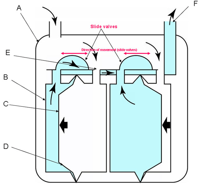
- Outer casing of the meter: Material: Zinc-coated steel sheet (soldered) with outside also lacquered.
- Casing of the identical twin chambers of the Meter. Material: Tinplate
- Non-flexible part of membrane. Material: Tinplate sheets. Flexible part of membrane.
- Material: Textile-reinforced nitrile rubber (Perbunan).
- Gas entry to the chamber.
- Gas outlet
Standard Equipment
- Twin-Chamber Measuring Unit
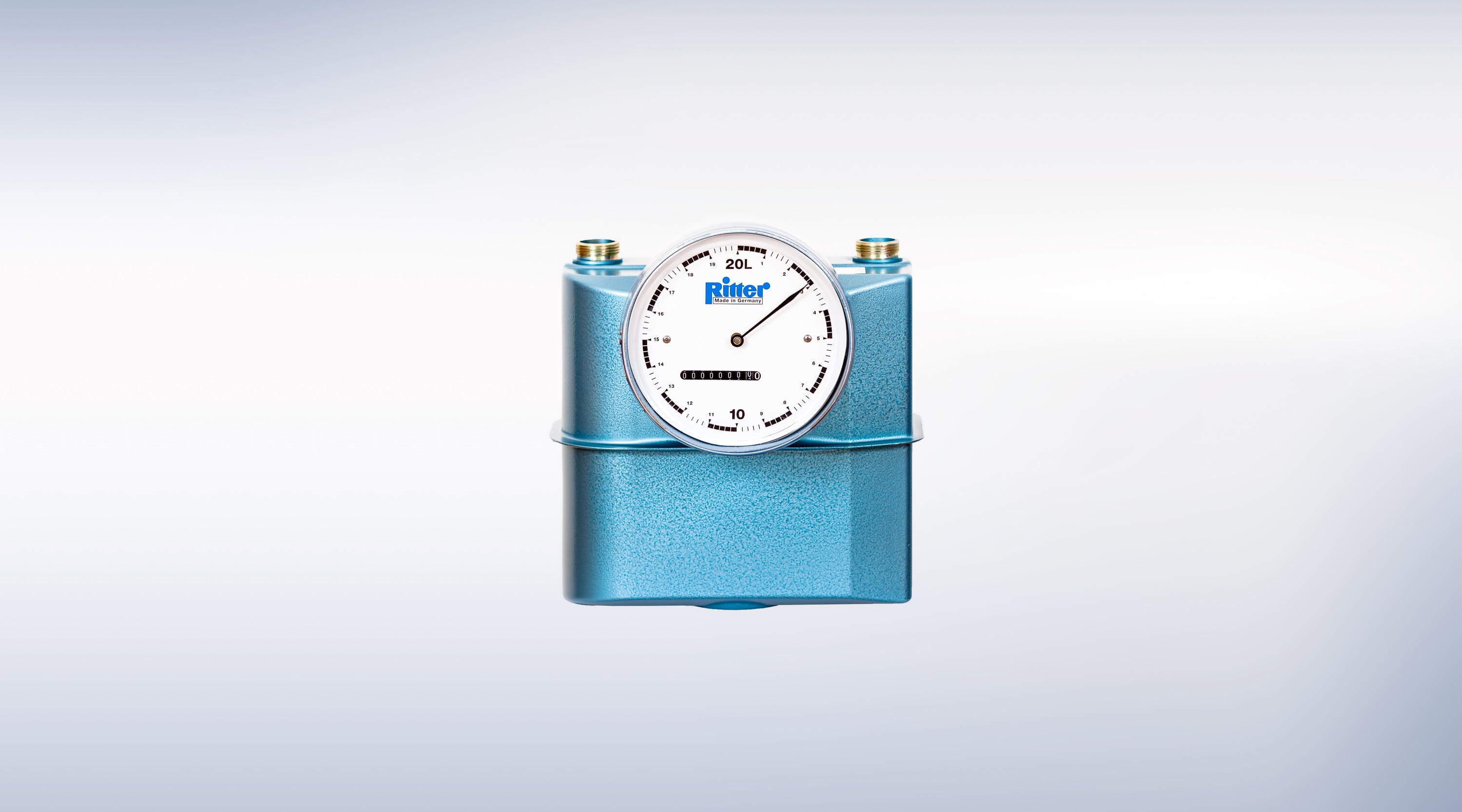
- 8 or 9-digit Totalizing Roller Counter
- Large One-needle Dial
- Magnetic Coupling (between measuring drum and counting mechanism)
- Gas Pipe Connection (inch thread)
Materials
Built-in Options
- LCD Display, resettable, 8-digit (replaces Totalizing Roller Counter)
- Pulse Generator, standard or Ex-proof version (for connecting Electronic Display Unit/Computer)
Accessories (external)
- Thermometer (BG)
- Manometer for pressure pmax = 60 mbar
- Electronic Display Unit »EDU 32 FP«, displays volume and calculates flow rate via RS232 and analog-output in realtime (pulse generator required)
- Nozzles for flexible tube connection


