- 1 General Specifications
- 2 Disadvantages of electrochemical (EC) sensors in comparison to the optical RITTER »MultiGas« Sensors
- 3 Preventive / Protective Measures with Gas Measurements
- 4 Scope of Supply
- 5 Setup
- 6 Infrared Sensors
- 7 Ultraviolet Sensors
- 8 Options (installed inside of the sensor casing)
General Specifications
Casing Types


Dimensions & Specifications
Casing Type 1 Casing Type 2 A 171 mm 444 mm B 290 mm (1) 305 mm C 86 mm 145 mm Weight, approx. (2) 2+ kg 6.5 – 8 kg Connections gas in-/outlet PVDF screw-type tube connection for tube Øi 4 mm, Øo 6 mm Connection tube PVC Rauclair Øi 4 mm, Øo 6 mm, 3 m Interfaces USB (standard), RS232 / CANbus / CANopen (options), MODbus on request Power supply 24 VDC, incl. plug-in power supply unit
100 – 240 VAC, 50/60 Hz
(2) Depending on type and number of built-in sensor modules
Interface specifications
USB
- Type: USB 2.0
- Connector: Type B
- Connecting cable: Type B /
type A
RS232
- Type: RS232
- Connector: D-sub9 female
- Connecting cable: D-sub9 1:1 male/male
CANopen
- Protocol type: CANopen mode 2
- Baudrate: 250 kBaud
- Node ID: 0x31
- Connector: RJ45
CANbus
- Protocol type: CANbus mode 1 (non standard)
- Baudrate: 250 kBaud
- Transmit ID: 0x208
- Receive ID: 0x300
- Connector: RJ45
MODbus
- Baudrate: 250 kBaud
- Databits: 8
- Stopbit: 1
- Parity: None
- Float Definition: IEE754
- Available registers:
- Read Holding Register 0x03
- Read Input Register 0x04
- Write Single Register 0x06
- Connector: RJ45
Assignment of Sensor Types to possible Sensor Combinations
Part 1: Pre‐configured Sensors incl. Casing Type 1
With gas connection fittings, data interface, plug-in power supply – ready for use
Sensor Type:
RITTER MultiGas xxxArticle
No.Group of Gases
IRNumber of Detectable Gases
in this GroupGroup of Gases
UVNumber of Detectable Gases
in this Group xxx = mono IR1 2678 1 xxx = duo IR2 2742 2 xxx = trio IR3 2743 3 xxx = mono UV1 2749 1 xxx = mono UV1
Cl2 30%2763 1 xxx = duo UV2 2766 2 xxx = duo IR1 + UV1 2797 1 1 xxx = trio IR1 + UV2 na 1 2
Part 2: Pre‐configured Sensors incl. Casing Type 2
With gas connection fittings, data interface, plug-in power supply – ready for use
Sensor Type:
RITTER MultiGas xxxArticle
No.Group of Gases
IRNumber of Detectable Gases
in this GroupGroup of Gases
UVNumber of Detectable Gases
in this Group xxx = mono UV1
H2S ≤ 5000 ppm2672 1 xxx = mono UV1
H2S ≤ 1%2855 1 xxx = UVRAS 2812 1 xxx = duo IR1
+ H2S ≤ 5000 ppm2959 1 1 xxx = duo IR1
+ (H2S ≤ 1% / NO)2960 1 1
Part 3: Individually combinable Sensor Modules
Composition according to customer specification, delivery incl. housing in suitable size according to number and type of modules – ready for use
Sensor Type:
RITTER MultiGas xxxArticle
No.Group of Gases
IRNumber of Detectable Gases
in this GroupGroup of Gases
UVNumber of Detectable Gases
in this Group xxx = Mod IR1 2813 1 xxx = Mod IR2 2814 2 xxx = Mod IR3 2815 3 xxx = Mod UV1 2830 1 xxx = Mod UV1
Cl2 30%na 1 xxx = Mod UV1
H2S ≤ 5000 ppm2841 1 xxx = Mod UV1
H2S ≤ 1%2856 1 xxx = Mod UV2 2831 2 xxx = Mod UVRAS 2917 3
Part 4: Casings for Sensor Modules
Assembled according to customer’s specification
Casing Type:
RITTER MultiGasArticle
No.Casing Type Suitable for xxx = Cas-2 (1) 2817 Casing Type 2 Multiple modules up to 444 x 305 x 145 mm xxx = Cas-3 (1) 2818 Casing Type 3 Multiple modules up to 444 x 305 x 189 mm
Part 5: Built‐in Options
Option Type:
RITTER MultiGasArticle
No.Description Range RMS-O2 (2) (3) 2795 Oxygen Sensor 0 ‐ 25% RMS-O2 (2) (3) 2767 Oxygen Sensor 0 – 100% RMS-O2-resist (3) 2824 Oxygen Sensor
H2S resistant0.5 – 35% RMS-P (2) (3) 2771 Pressure Sensor 800 – 1200 mbar abs.
Resolution <1 mbar RMS-P-resist (3) 2825 Pressure Sensor
H2S resistant0.2 – 3.5 bar abs.
Resolution 2 mbar RMS-H (2) (3) 2773 Humidity Sensor 0 – 100% RH RMS-A/O 2648 Analog Voltage Output
0-2 V / 0-5 V / 0-10 V4 Analog output ports for 4 separate gas concentrations
16 bit RMS‐CasHeat 2954 Thermostated Casing Heating and thermostatting of the sensor casing at 45 °C
(3) Available as supplement to IR or UV Sensor only
Part 6: Accessories / Options
Option Type:
RITTER MultiGas xxxArticle
No.Description Range xxx = Cal-ZP-N2 2805 Calibration Gas N2 For zero-point calibration of all gases xxx = Flow-V 2806 Mini Flow Valve Control of flow rate for calibration gas bottle
Incl. Manometer xxx = Cal-CG-Cat1 2948 Calibration with special carrier gas (Ar, H2, He)
for gases category 1Category 1 gases:
xxx = Cal-CG-Cat2 2949 Calibration with special carrier gas (Ar, H2, He)
for gases category 2Category 2 gases:
xxx = Cal-ReCal-Cat1 2950 Recalibration for gases category 1 Category 1 gases:
xxx = Cal-ReCal-Cat2 2951 Recalibration for gases category 2 Category 2 gases:
Infrared module NDIR Ultraviolet module NDUV
Calibrations
Depending on the number of gases to be analysed, a suitable calibration gas must be selected. Furthermore, the type of gas also influences the optimal calibration gas. Because of the almost infinite number of possible combinations, the following list should therefore only be understood as a first overview.
Measurement of Humid Gases
When measuring humid gases, it is essential to prevent condensation of the water vapour inside the sensor. The following diagram shows the maximum water vapour concentration ( = absolute humidity) in volume % as a function of temperature at the standard pressure 1013 mbar.
The diagram shows:
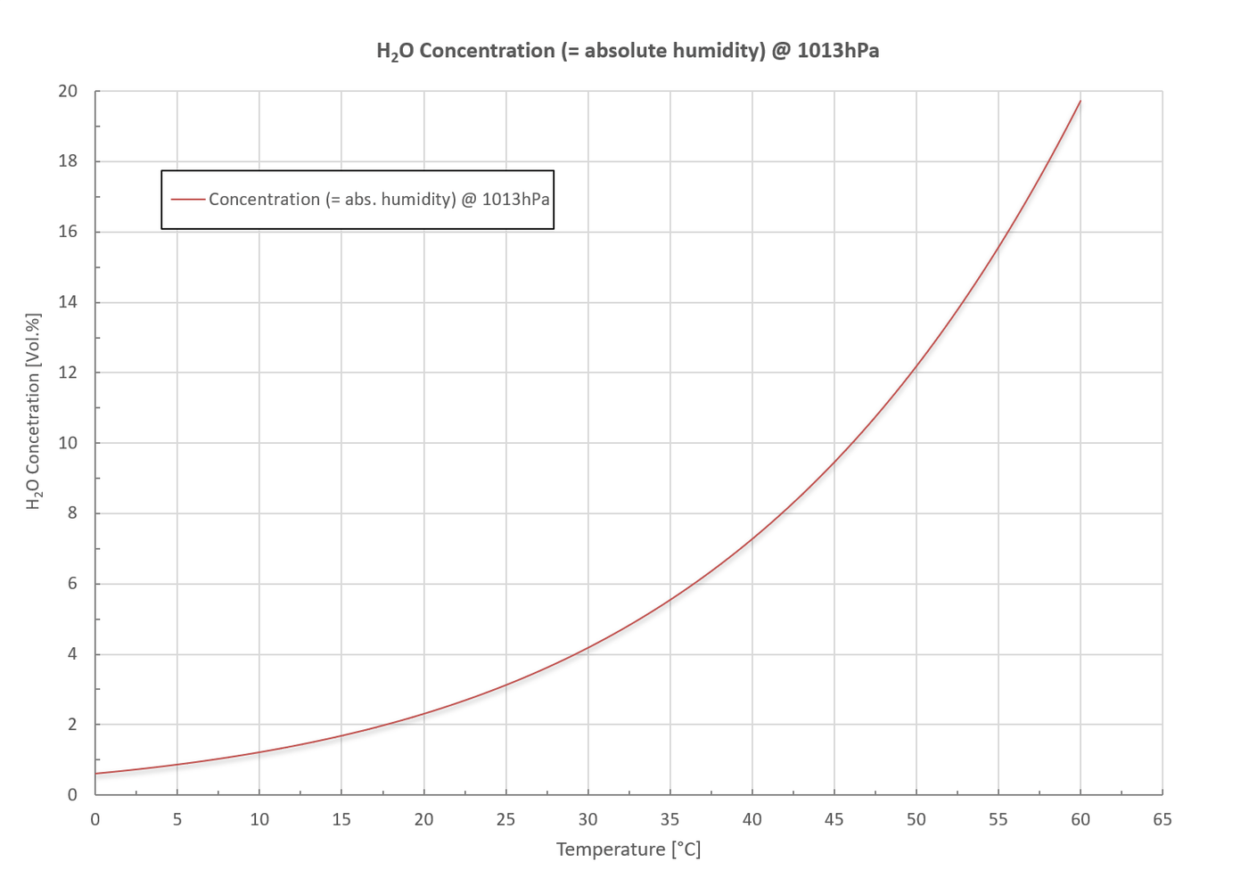
Condensation can be prevented by the following measures:
With the optional Humidity Sensor the relative humidity can be measured in the measuring range of 0 ~ 100% rH. Furthermore, the absolute humidity can be measured as well in g/m³. Both values are displayed in the supplied software.
Disadvantages of electrochemical (EC) sensors in comparison to the optical RITTER »MultiGas« Sensors
Preventive / Protective Measures with Gas Measurements
Important: Please specify the desired options when ordering
a) Additional tube connection for flushing of the casing
The gas lines inside the casing and the measuring cuvette are gas-tight by means of O-rings and other gas-tight connections. However, as with all connections, a leakage rate, however slight, cannot be ruled out. With an additional tube connection for flushing of the casing, an accumulation of the measuring gas inside the casing can be prevented.
In the case of toxic or aggressive gases, a suction line can be connected via this tube connection, which creates a under-pressure inside the housing thus preventing the gas from escaping from the casing.
In case of ignitable gases (methane, hydrogen, etc.), a pressure or suction line can be connected via this tube connection creating an over- or under-pressure inside the casing thus preventing the accumulation of an ignitable gas mixture.
Please note: H2S can be perceived as an unpleasant smell even in the ppb range. Even with an O-ring seal, micro-leaks can occur, which can be extracted by flushing the housing.
b) Heated and thermostatted casing
Condensation of the measuring gas inside of the sensor must be prevented. This can generally be achieved with a condensation trap or gas cooler. Please also refer to »Measurement of Humid Gases«. Alternatively, the inside of the sensor casing can be heated and thermostatted at 45 °C (standard). The heating not only avoids condensation inside of the sensor but ensures constant measurement results as well. See »Heating and Thermostatting of Sensor Casing«.
c) Particle filter
Please make sure by use of a suitable filter that no particles are carried into the sensor. These might block the small openings of the internal fittings. It is recommended to use filters of 5 micron or smaller.
Scope of Supply
| No. of Items | Item |
|---|---|
| 1 | Document folder including: Calibration Certificate / Data Sheets / Software Manual |
| 1 | Sensor in table top casing |
| 1 | Plug-in power supply unit Input: 100 – 240 V-AC, 50/60 Hz, 0.4 A Output: 24 V-DC, 0.5 A, 12 W or 36 W (H2S / UVRAS Sensor) |
| 1 | Data acquisition software (on USB memory card) |
| 1 | Connection cable: Sensor → PC Standard: USB V2.0 A/B, 1 m Option: RS232, 3m |
| 3m | Viton tubing Øi 4mm / Øo 6mm |
Setup
- Unpack all items carefully.
- Install the data acquisition software according to the »RITTER MultiGas Software Manual«.
Don’t start the software at this point in time. - Positioning of the sensor:
- If the sensor is used in combination of a RITTER MilliGascounter, the sensor must be positioned (in flow direction) in front of the MilliGascounter if this MilliGascounter is filled with HCl solution. Otherwise, the sensor could be damaged by the HCl vapour coming out of the MilliGascounter.
- Place the sensor next to the gas source.
Please note: A tube connection between gas source and sensors that is as short as possible allows a small dead space created by the tubing. In turn, a small dead space enables a fast response time of the sensor.
- Connect the power adapter to socket »DC 24 V« at the rear side of the sensor and to mains.
- Connect the data acquisition cable to the respective socket at the rear side of the sensor and to the computer:
- USB cable to the socket »USB«
- RS232 cable to the socket »RS 232« (option)
- Connect the gas source to the gas inlet port of the sensor by using the provided tubing as follows:
- Remove the screw caps as well as the red rubber caps of the transport lock from the gas inlet and gas outlet.
- Slide the screw cap onto the end of the gas inlet tube with the thread of the screw cap facing the tube end.
- Push the tube onto the cone in the center of the gas inlet port.
- Slide the screw cap on the gas inlet port and screw it in place hand-tight.
- If applicable: Connect the gas outlet port of the sensor to other components such as gas sampling bags, exhaust tubing etc. The connection of the tube on the gas outlet port takes place in the same way as described above.
- Switch-on the power switch at the front side of the sensor casing.
- Start the software and open the COM port(s) of the connected sensor module(s) according to the software manual.
The RITTER »MultiGas« Sensor is now ready for use.
Infrared Sensors
MultiGas Infrared Module NDIR
Description
Gas analysis based on the NDIR technique is an established method to determine the concentrations of gases in complex mixtures. The RITTER »MultiGas« sensors use new optical components for optimal analysis results: Up to 3 optical filters analyse the gas which flows through the sensor as one gas stream. The optional oxygen, pressure, and humidity sensors are in-line with the same single gas stream.
The individual internal modules are sealed by means of O-ring connections.
In order to achieve an optimum adaptation to the required measuring range, the lengths of the modular measurement cells (= cuvettes) can be implemented in the range of 5 mm (large measurement range in percentage level) up to 250 mm (small measurement range in ppm level).
Cuvettes with a length ≥ 20 mm are coated with a resistant gold layer in order to improve the reflection properties for low concentration level detection and offer additional protection against slightly corrosive gases. Cuvettes used with aggressive gases are gold-coated as well.
The other internal mechanical parts are made out of aluminium, optionally out of stainless steel.
For fast response applications the measuring system delivers a stable result within t90 ≈ 3 seconds.
The entire unit can be disassembled for easy maintenance/service.
Applications
Specifications
General features
| Measurement technology: | Innovative NDIR Sensor (non-dispersive infrared sensor) |
| Detectable gases: | CO2 CO N2O CnHm CH4 CF4 SF6 H2O |
| Number of simultaneously detectable gases: | max. 3 per sensor unit |
| Measurement ranges: | See Table of Measurement Ranges |
| Flow rate range: | 5 ~ 300 ltr/h For higher flow rates the sensor can be operated in bypass |
| Max. gas inlet pressure: | 300 mbar |
| Pressure loss (without additional optional sensors): | 10 @ 100 / 35 @ 200 / 70 @ 300 (mbar @ ltr/h) |
| Temperature compensation: | Yes |
| Data acquisition software: | Yes |
| Lifetime of IR radiation source: | > 40 000 h |
| Measurement cuvette: | Aluminium, with measurement ranges ≤1% gold-plated inside |
| Cuvette sealing: | Viton O-ring |
| Casing: | High-quality table-top casing, aluminium |
| Dimensions (W x H x L): | 171 x 86 x 290 mm |
| Weight: | approx. 2 kg |
| Gas connections: | PVDF screw-type tube connection for tube Øi 4 mm, Øo 6 mm |
Measurement data
| Linearity error: | < ± 1% F.S. |
| Repeatability: | ± 0.5% F.S. |
| Long term stability zero: | < ± 2% F.S. / week |
| Long term stability span: | < ± 2% F.S. / month |
| Temperature influence of zero point: | < 1% F.S. / 10K |
| Temperature influence of span: | < 2% F.S. / 10K |
| Cross sensitivity: | < 2% F.S. |
| Pressure influence: | < 1.5% / 10hPa of reading |
| Warm-up time: | 2 min |
| Response time (t90): | ≈ 3 sec |
| Sampling frequency by software: | ≤ 10 Hz |
| Detection limit: | See Table of Detection Limits |
| Resolution: | 0.5 x detection limit |
| Water vapour: | No influence with measurements of CO2 and CH4 |
Electrical features
| Power supply: | 24 VDC incl. power plug 100 ~ 240 VAC 50/60 Hz: 24 VDC |
| Average power consumption: | < 1W |
| Interface: | USB (standard), RS232 / CANbus / CANopen (options) incl. data transmission cable 1 m |
| Analogue voltage output (option): | 0 – 2 V / 0 – 5 V / 0 – 10 V |
Gas parameters
| Operating temperature: | +15 ~ +45 °C |
| Storage temperature: | –20 ~ +60 °C |
| Operating pressure: | 800 ~ 1200 hPa (mbar) |
| Ambient humidity: | 0 ~ 95% rel. humidity Condensing inside of sensor must be prevented! |
* Analysis of CnHm: The calibration of sensors for CnHm will be performed with propane. Aromatic hydrocarbons are also measured but with a different weighting. This means that the sensitivity of the sensor is significantly smaller with these gases than with other hydrocarbons.
List of standard measurement ranges *1 ( and detection limits *2 )
| Standard Measuring Ranges with respective Detection Limits ( % of F.S. *3 ) | ||||||||||||||||
|---|---|---|---|---|---|---|---|---|---|---|---|---|---|---|---|---|
| 100 Vol.% | 50 Vol.% | 30 Vol.% | 20 Vol.% | 10 Vol.% | 5 Vol.% | 1 Vol.% | 5,000 ppm | 2,000 ppm | 1,000 ppm | 500 ppm | 300 ppm | 100 ppm | 50 ppm | 10 ppm | 1 ppm | |
| CO2 | (< 0.1%) | (< 0.1%) | (< 0.1%) | (< 0.1%) | (< 0.1%) | (< 0.1%) | (< 0.1%) | (< 0.1%) | (< 0.1%) | (< 0.1%) | (< 0.3%) | (< 0.3%) | ||||
| CO | (< 0.2%) | (< 0.2%) | (< 0.2%) | (< 0.2%) | (< 0.2%) | (< 0.2%) | (< 0.2%) | (< 0.3%) | (< 0.5%) | (< 0.5%) | ||||||
| N2O | (< 0.1%) | (< 0.1%) | (< 0.1%) | (< 0.1%) | (< 0.1%) | (< 0.1%) | (< 0.1%) | (< 0.3%) | ||||||||
| CnHm*4 | (< 0.1%) | (< 0.1%) | (< 0.1%) | (< 0.2%) | (< 0.2%) | (< 0.2%) | (< 0.2%) | (< 0.5%) | (< 0.5%) | |||||||
| CH4 | (< 0.1%) | (< 0.1%) | (< 0.1%) | (< 0.1%) | (< 0.1%) | (< 0.1%) | (< 0.1%) | (< 0.3%) | (< 0.5%) | |||||||
| CF4 | (< 0.2%) | (< 0.2%) | (< 0.2%) | (< 0.02%) | (< 0.05%) | |||||||||||
| SF6 | (< 0.1%) | (< 0.1%) | (< 0.1%) | (< 0.2%) | (< 0.5%) | (< 0.3%) | (< 0.3%) | |||||||||
| H2O | ||||||||||||||||
Infrared module NDIR Ultraviolet module NDUV
Definition of Detection Limit
The Detection Limit is the smallest measurement value which can be obtained with a specific uncertainty. This uncertainty includes the resolution, noise and stability of the gas sensor for a specific gas and specific measurement range. For evaluation of the detection limit value, several single measurements are taken at the identical measurement conditions. With the obtained single measurement results the standard deviation “Sigma” (σ) is calculated. The values given in the table equal the triple amount of Sigma.
Recalibrations
The following recalibration intervals are recommended for IR sensors:
Ultraviolet Sensors
The RITTER »MultiGas« UV sensor is the world’s first gas analysis module based on miniaturized UV-LEDs. The stability and lifetime of these UV-LEDs enables high-precision gas analysis down to the ppm range. By using two UV-LEDs two gases can be detected simultaneously. Furthermore, with this approach measuring ranges from ppm to Vol.-% can be realized. In the spectral range from 200 nm to 500 nm, nitrogen oxides (NO + NO2), aromatic hydrocarbons, hydrogen sulphide, ozone, sulphur dioxide and chlorine can be reliably detected with this new sensor platform. The entire unit can be disassembled for easy maintenance/service. The individual internal modules are sealed by means of O-ring connections. In order to achieve an optimum adaptation to the required measuring range, the lengths of the modular measurement cells (= cuvettes) can be implemented in the range of 5 mm (large measurement range in percentage level) up to 250 mm (small measurement range in ppm level). Cuvettes with a length ≥ 20 mm are coated with a resistant gold layer in order to improve the reflection properties for low concentration level detection. Cuvettes used with aggressive gases are gold-coated as well. The internal mechanical parts are made out of aluminium, optionally out of stainless steel. For fast response applications the measuring system delivers a stable result within t90 ≈ 1-2 seconds. Infrared module NDIR Ultraviolet module NDUV Definition of Detection Limit The Detection Limit is the smallest measurement value which can be obtained with a specific uncertainty. This uncertainty includes the resolution, noise and stability of the gas sensor for a specific gas and specific measurement range. For evaluation of the detection limit value, several single measurements are taken at the identical measurement conditions. With the obtained single measurement results the standard deviation “Sigma” (σ) is calculated. The values given in the table equal the triple amount of Sigma. The following recalibration intervals are recommended for UV sensors: For the detection of NO an EDL (electrodeless gas discharge lamp) is used. In the EDL, N2 and O2 are converted to NO and produce a selective UV radiation. With this radiation, a cross-sensitivity-free NO measurement is made possible. This method is called UV resonance absorption spectroscopy (UVRAS). A combination of both the UVRAS and NDUV technology allows the simultaneous gas analysis of NO, NO2 and SO2 in the lower ppm range which is particularly important in flue gas analysis (Continuous Emission Monitoring, CEM). Infrared module NDIR Ultraviolet module NDUV Definition of Detection Limit The Detection Limit is the smallest measurement value which can be obtained with a specific uncertainty. This uncertainty includes the resolution, noise and stability of the gas sensor for a specific gas and specific measurement range. For evaluation of the detection limit value, several single measurements are taken at the identical measurement conditions. With the obtained single measurement results the standard deviation “Sigma” (σ) is calculated. The values given in the table equal the triple amount of Sigma. The following recalibration intervals are recommended for UV sensors: The H2S sensor works according to the principle of non-dispersive UV absorption (NDUV). The measuring wavelength used is in the lower nanometer range, which enables interference-free measurements with water vapour and hydrocarbons. This makes the sensor ideal for use in biogas measurements, as accompanying gases such as NH3, CO2, CH4 and H2O do not affect the accuracy of the measurements. In contrast to photometric NDUV sensors the lifetime of electrochemical sensors for measurement of H2S is limited. Please note that lifetime data for such sensors are given for air and not for measurement of H2S. For H2S concentrations > 200 ppm the lifetime is reduced, for concentrations > 1000 ppm critical. While the measurement performance of UV-LED is constant, EC sensors are becoming »deaf«. Infrared module NDIR Ultraviolet module NDUV Definition of Detection Limit The Detection Limit is the smallest measurement value which can be obtained with a specific uncertainty. This uncertainty includes the resolution, noise and stability of the gas sensor for a specific gas and specific measurement range. For evaluation of the detection limit value, several single measurements are taken at the identical measurement conditions. With the obtained single measurement results the standard deviation “Sigma” (σ) is calculated. The values given in the table equal the triple amount of Sigma. The following recalibration intervals are recommended for UV sensors: The oxygen sensor is only available as an additional sensor module to a RITTER »MultiGas« NDIR or NDUV sensor. The measured oxygen concentration is displayed in the provided software. The sensor is built into the casing of the RITTER »MultiGas« sensors. The following versions are available: * related to Pa = 1013 hPa, Ta = 25 °C, RH = 50%, flow = 2.5 l/min A change in the gas and/or atmospheric pressure causes a change in the number of molecules per volume and thus a change in gas density. This density change in turn has a significant influence on the result of the concentration measurement by the sensor. By measuring the gas pressure inside of the sample cell (cuvette), the value of the concentration measurement is compensated / corrected. The pressure sensor enables an increase in the accuracy of the gas analysis measurement by a factor of 15: The pressure sensor is always integrated into the RITTER »MultiGas« NDIR sensors as a micro-sensor. It is optionally available for the NDUV sensors and is built into the sensor casing. The measured pressure value is displayed in the provided software. For non-aggressive gases: For H2S and similar acid gases: The humidity sensor is only available as an additional sensor module to a RITTER »MultiGas« NDIR or NDUV sensor. The sensor is built into the casing of the RITTER »MultiGas« sensors. The measured humidity values (absolute and relative) are displayed in the provided software. The Analog Voltage Output Module allows the simultaneous output of up to 4 different values at 4 separate channels: For connection to an analog data acquisition device the analog voltage output port alternatively provides the following voltage levels: The voltage range is pre-set according to the order and cannot be changed by the user. Please note the assignments of the respective gas concentration measurements to the respective channels. These assignments are stated in the Calibration Protocol of the sensor unit. Assignment of contacts to the channels of the gas concentration measurements at the socket and plug of the Analog Voltage Output: Analogue output signals of oxygen and humidity sensors: Only one of these two signals can be transmitted alternatively. The connection cable is delivered with open wires to be connected to the analog data acquisition device of the user. The wire colours are listed in the above table. In order to avoid condensation of humid gas inside of the sensor, the sensor and sensor casing can be heated and thermostatted. By default, the temperature controller is preset to 45 °C; lower temperatures are possible on request. The heating element and temperature controller are mounted at the support of the measurement cuvette. The filter for gas particles is provided as an accessory for those applications where no additional gas filtration is performed by the user. It is designed as an inline filter which can easily inserted in the gas tubing in front of all RITTER »MultiGas« Sensors. Please note: It is essential that particles do not enter the sensor as this will block the small openings inside the sensor. Each sensor is supplied with one filter per gas line. The filter is inserted into the supply tube using a tube screw connection. Additional filters can be ordered from your national RITTER Distribution Partner. MultiGas Ultraviolet Module NDUV
Description
Applications
Specifications
General features
Measurement technology: Innovative NDUV Sensor
(non-dispersive ultraviolet sensor)Detectable gases: Number of simultaneously detectable gases: max. 2 Measurement ranges: See Table of Measurement Ranges Flow rate range: 5 ~ 300 ltr/h
For higher flow rates the sensor can be operated in bypassMax. gas inlet pressure: 300 mbar Pressure loss (without additional optional sensors): 10 @ 100 / 35 @ 200 / 70 @ 300 (mbar @ ltr/h) Temperature compensation: Yes Data acquisition software: Yes Lifetime of UV radiation source: > 8 000 h Measurement cuvette: Stainless steel with silicone coating inside Cuvette sealing: Viton O-ring Internal tubing: FKM / Viton (fluorinated rubber) Casing: High-quality table-top casing, aluminium Dimensions (W x H x L): 464 x 189 x 305 mm Weight: approx. 6.5+ kg Gas connections: PVDF screw-type tube connection for tube Øi 4 mm, Øo 6 mm Measurement data
Linearity error: < ± 1% F.S. Repeatability: ± 0.5% F.S. Long term stability zero: < ± 1% F.S. / 24 h Long term stability span: < ± 1% F.S. / month Temperature influence of zero point: < 1% F.S. / 10K Temperature influence of span: < 2% F.S. / 10K Cross sensitivity: < 2% F.S. Pressure influence: < 1.5% / 10 hPa of reading Warm-up time: 1 min (initial), < 60 min for full specification Response time (t90): 1.5 – 15 sec Sampling frequency by software: ≤ 10 Hz Detection limit: See Table of Measurement Ranges Resolution: 0.5 x detection limit Electrical features
Power supply: 24 VDC incl. power plug 100 ~ 240 VAC
50/60 Hz: 24 VDC Supply current (peak) < 0.4 A Average power consumption < 7.5 W Interface: USB (standard)
RS232 / CANbus / CANopen (options)
incl. data transmission cable 1 m Analogue voltage output (option): 0-2 V / 0-5 V / 0-10 V Gas parameters
Operating temperature: +25 ~ +45 °C Storage temperature: –20 ~ +60 °C Operating pressure: 800 ~ 1200 hPa (mbar) Ambient humidity: 0 ~ 95% rel. humidity
Condensing inside of sensor must be prevented!List of standard measurement ranges *1 ( and detection limits *2 )
Standard Measuring Ranges with respective Detection Limits ( % of F.S. *3 ) 100
Vol.%50
Vol.%30
Vol.%20
Vol.%10
Vol.%5
Vol.%1
Vol.%5,000
ppm2,000
ppm1,000
ppm500
ppm300
ppm100
ppm50
ppm10
ppm1
ppm O3
(< 0.1%)
(< 0.1%)
(< 0.1%)
(< 0.2%)
(< 0.5%)
(< 0.5%)
(< 0.5%) CL2
(< 0.1%)
(< 0.1%)
(< 0.1%)
(< 0.1%)
(< 0.1%)
(< 0.1%)
(< 0.1%)
(< 0.2%)
(< 0.5%) SO2
(< 0.1%)
(< 0.1%)
(< 0.1%)
(< 0.1%)
(< 0.1%)
(< 0.1%)
(< 0.1%)
(< 0.1%)
(< 0.5%)
(< 0.5%)
(< 0.5%) H2S
(< 0.1%)
(< 0.1%)
(< 0.1%)
(< 0.1%)
(< 0.2%)
(< 0.5%) NO2
(< 0.1%)
(< 0.1%)
(< 0.1%)
(< 0.2%)
(< 0.2%)
(< 0.5%)
(< 0.5%)
(< 0.5%) NO
(< 0.1%)
(< 0.1%)
(< 0.1%)
(< 0.2%)
(< 0.2%) Recalibrations
MultiGas Ultraviolet Module NDUV / UVRAS
Description
Applications
Specifications
General features
Measurement technology: UV resonance absorption spectroscopy (UVRAS) Detectable gases: Number of simultaneously detectable gases: max. 3 per sensor unit Measurement ranges: See Table of Measurement Ranges Flow rate range: 5 ~ 300 ltr/h
For higher flow rates the sensor can be operated in bypassMax. gas inlet pressure: 300 mbar Pressure loss (without additional optional sensors): 10 @ 100 / 35 @ 200 / 70 @ 300 (mbar @ ltr/h) Additional heated and thermostatted enclosure inside of sensor casing: Yes Temperature compensation: Yes Data acquisition software: Yes Lifetime of UV radiation sources: LED > 20 000 h (NO2, SO2)
EDL > 8 000 h (NO)Measurement cuvette: Stainless steel with silicone coating inside Cuvette sealing: Viton O-ring Internal tubing: FKM / Viton (fluorinated rubber) Casing: High-quality table-top casing type 2, aluminium Dimensions (W x H x L): 464 x 189 x 305 mm Weight: approx. 6.5+ kg Gas connections: PVDF screw-type tube connection for tube Øi 4 mm, Øo 6 mm Measurement data
Linearity error: < ± 1% F.S. Repeatability: ± 0.5 % F.S. Long term stability zero: < 3 ppm / 24 h Long term stability span: < ± 1 % F.S. / month Temperature influence of zero point: < 1 % F.S. / 10 K Temperature influence of span: < 2 % F.S. / 10 K Cross sensitivity: 500 ppm NO2 < 2 ppm
100 ppm SO2 < 2 ppm
100 ppm N2O < 10 ppm
20 °C D.P. H2O < 10 ppm
Pressure influence: < 1.5% / 10 hPa of reading Warm-up time: 1 min (initial), < 60 min for full specification Response time (t90): 1.5 ~ 15 sec Sampling frequency by software: ≤ 10 Hz Detection limit: See Table of Measurement Ranges Resolution: 0.5 x detection limit Electrical features
Power supply: 24 VDC incl. power plug 100 ~ 240 VAC
50/60 Hz: 24 VDCSupply current (peak): 1.5 A Inrush current: 0.2 ~ 0.7 A Power consumption: 36 W Interface: USB (standard)
RS232 / CANbus / CANopen (options)
incl. data transmission cable 1 mAnalogue voltage output (option): 0-2 V / 0-5 V / 0-10 V Gas parameters
Operating temperature: +5 ~ +40 °C Storage temperature: –20 ~ +60 °C Operating pressure: 800 ~ 1200 hPa (mbar) Ambient humidity: 0 ~ 95% rel. humidity
Condensing inside of sensor must be prevented!List of standard measurement ranges *1 ( and detection limits *2 )
Standard Measuring Ranges with respective Detection Limits ( % of F.S. *3 ) 100
Vol.%50
Vol.%30
Vol.%20
Vol.%10
Vol.%5
Vol.%1
Vol.%5,000
ppm2,000
ppm1,000
ppm500
ppm300
ppm100
ppm50
ppm10
ppm1
ppm SO2
(< 0.1%)
(< 0.1%)
(< 0.1%)
(< 0.1%)
(< 0.1%)
(< 0.1%)
(< 0.1%)
(< 0.1%)
(< 0.5%)
(< 0.5%)
(< 0.5%) NO2
(< 0.1%)
(< 0.1%)
(< 0.1%)
(< 0.2%)
(< 0.2%)
(< 0.5%)
(< 0.5%)
(< 0.5%) NO
(< 0.1%)
(< 0.1%)
(< 0.1%)
(< 0.2%)
(< 0.2%) Recalibrations
MultiGas Ultraviolet Module NDUV / H2S
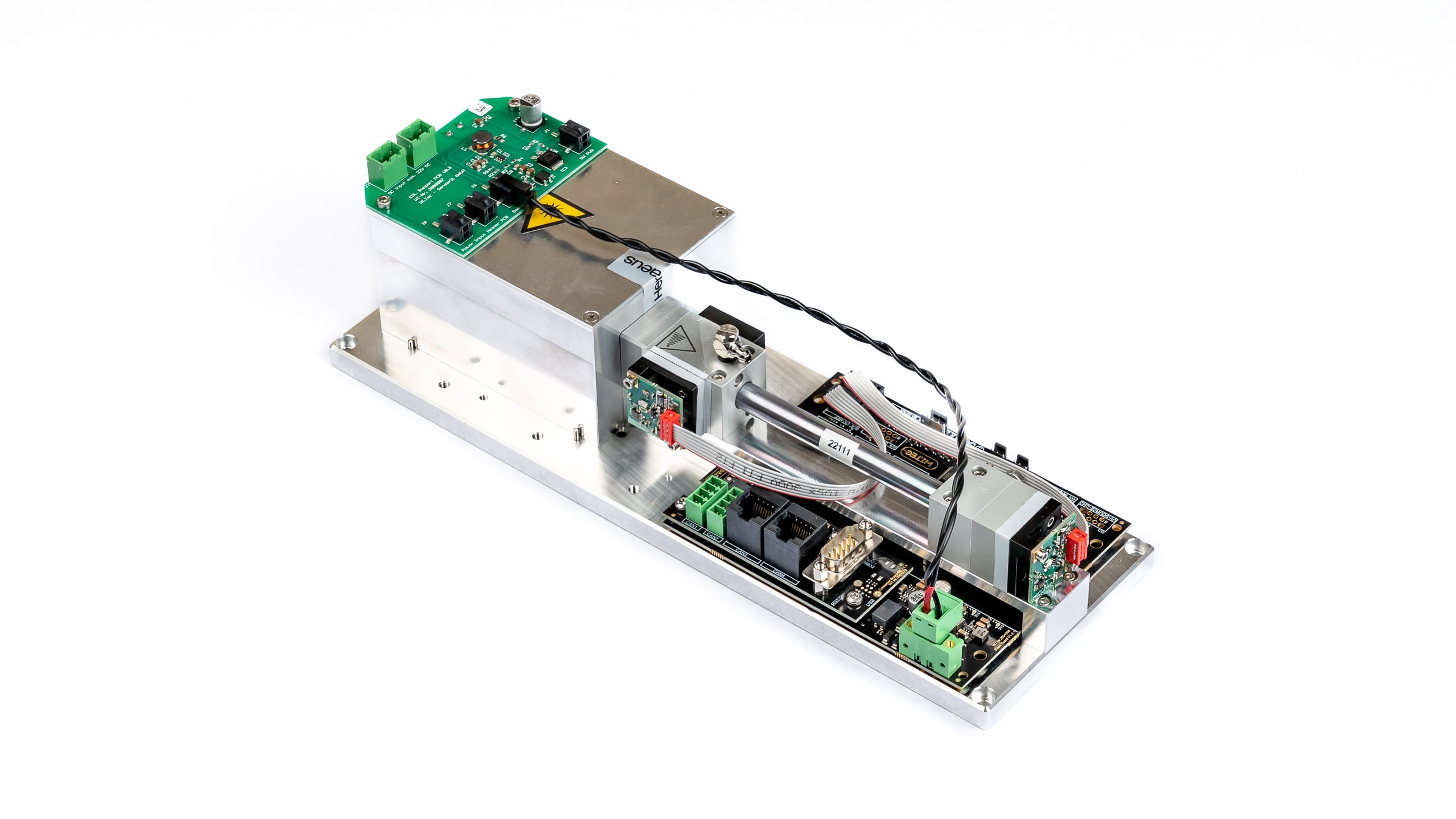
Description
Applications
Specifications
General features
Measurement technology: Innovative NDUV Sensor
(non-dispersive ultraviolet sensor)
Dual beamDetectable gases: Number of simultaneously detectable gases: max. 2 Measurement ranges: See Table of Measurement Ranges Flow rate range: 5 ~ 300 ltr/h
For higher flow rates the sensor can be operated in bypassMax. gas inlet pressure: 300 mbar Pressure loss (without additional optional sensors): 10 @ 100 / 35 @ 200 / 70 @ 300 (mbar @ ltr/h) Temperature compensation: Yes Data acquisition software: Yes Lifetime of UV radiation source: > 8 000 h Measurement cuvette: Stainless steel with silicone coating inside Cuvette sealing: Viton O-ring Internal tubing: FKM / Viton (fluorinated rubber) Casing: High-quality table-top casing, aluminium Dimensions (W x H x L): 300 x 100 x 81 mm Weight: approx. 1670 g Gas connections: PVDF screw-type tube connection for tube Øi 4 mm, Øo 6 mm Measurement data
Linearity error: < ± 1% F.S. Repeatability: ± 0.5% F.S. Long term stability zero: < ± 1% F.S. / 24 h Long term stability span: < ± 1% F.S. / month Temperature influence of zero point: < 1% F.S. / 10K Temperature influence of span: < 2% F.S. / 10K Cross sensitivity: < 2% F.S. Pressure influence: < 1.5% / 10 hPa of reading Warm-up time: 1 min (initial), < 15 min for full specification Response time (t90): 1.5 – 15 sec Sampling frequency by software: ≤ 10 Hz Detection limit: See Table of Measurement Ranges Resolution: 0.5 x detection limit Electrical features
Power supply: 24 VDC incl. power plug 100 ~ 240 VAC
50/60 Hz: 24 VDC Supply current (peak): < 0.4 A Average power consumption: < 7.5 W Interface: USB (standard)
RS232 / CANbus / CANopen (options)
incl. data transmission cable 1 m Analogue voltage output (option): 0-2 V / 0-5 V / 0-10 V Gas parameters
Operating temperature: +5 ~ +45 °C Storage temperature: –20 ~ +60 °C Operating pressure: 800 ~ 1200 hPa (mbar) Ambient humidity: 0 ~ 95% rel. humidity
Condensing inside of sensor must be prevented!List of standard measurement ranges *1 ( and detection limits *2 )
Standard Measuring Ranges with respective Detection Limits ( % of F.S. *3 ) 100
Vol.%50
Vol.%30
Vol.%20
Vol.%10
Vol.%5
Vol.%1
Vol.%5,000
ppm2,000
ppm1,000
ppm500
ppm300
ppm100
ppm50
ppm10
ppm1
ppm SO2
(< 0.1%)
(< 0.1%)
(< 0.1%)
(< 0.1%)
(< 0.1%)
(< 0.1%)
(< 0.1%)
(< 0.1%)
(< 0.5%)
(< 0.5%)
(< 0.5%) H2S
(< 0.1%)
(< 0.1%)
(< 0.1%)
(< 0.1%)
(< 0.2%)
(< 0.5%) Recalibrations
Options (installed inside of the sensor casing)
Oxygen Sensor
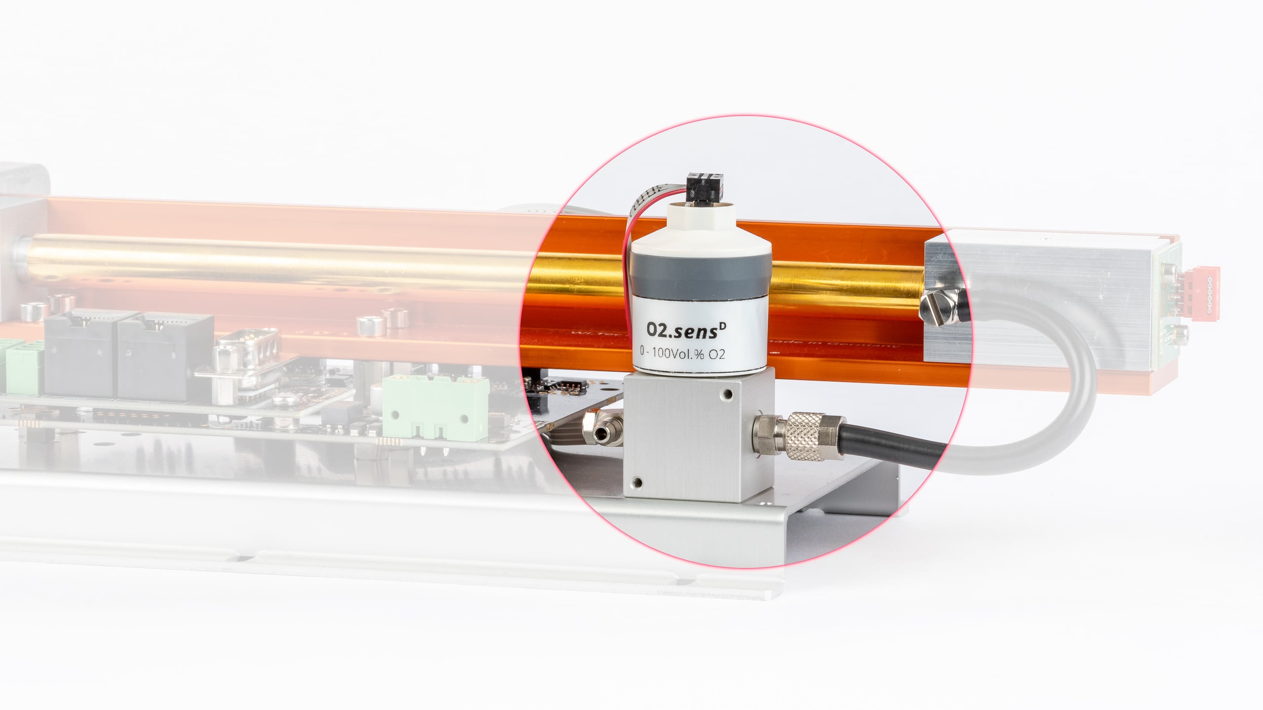
Overview
Specifications
General features
Version Standard version H2S resistant version Measurement range 0 – 25 Vol.% O2 0 – 100 Vol.% O2 0.5 – 35 Vol.% O2 Application Biogas, Automotive exhaust gas analyser Industrial, fully CO2 resistant Industrial, fully CO2 resistant,
shows high resistance to acid gasesMedium contact materials ABS, FKM, PPS, PTFE, stainless steel ABS, PVC, PPS, PTFE, stainless steel ABS, PVC, PPS, PTFE,
stainless steelExpected operating life 1,000,000 Vol.% O2 h ~ 1,200,000 Vol.% O2 h ~ 1,200,000 Vol.% O2 h Sensor lifetime 4 years at ambient air,
depending on application6 years at ambient air,
depending on application6 years at ambient air Dimensions
(H x W x L)65.4 mm × 31.7 mm × 56.6 mm Weight 70 g Tube connector 4/6 mm tube Measurement data *
Version Standard version H2S resistant version Measurement range 0 – 25 Vol.% O2 0 – 100 Vol.% O2 0.5 – 35 Vol.% O2 Resolution 0.1 Vol.% 0.1 Vol.% 0.1 Vol.% Response time (t90) < 3.5 s < 10 s < 5 s Drift ** < 1% per month < 1% per month < 3% per month Linearity Error 0 – 2 Vol.% O2: ± 0.1 abs.
2.1 – 100 Vol.% O2: ± 0.05 rel.0 – 2 Vol.% O2: ± 0.1 abs.
2.1 – 35 Vol.% O2: ± 0.05 rel.Repeatability *** ± 1 Vol.% O2 ± 1 Vol.% O2 Influence of Humidity –0.03 % rel. O2 reading /
% RH–0.03 % rel. O2 reading /
% RH–0.03 % rel. O2 reading /
% RHInterferences CO2: up to 20 Vol.%
CO: up to 2000 ppm
NOx: up to 5000 ppm
HC: up to 5000 ppm
N2O: up to 500 ppm< 20 ppm O2 response to:
100 Vol.% CO
100 Vol.% CO2
100 Vol.% C3H8
3000 ppm NO in N2
1000 ppm C6H6 in N2
500 ppm SO2 in N2
< 100 ppm O2 response to:
3000 ppm C2H6O
3000 ppm C4H10S
< 200 ppm O2 response to:
3000 ppm C2H6S2
< 400 ppm O2 response to:
100 Vol.% H2
< 500 ppm O2 response to:
2000 ppm H2S in N2< 20 ppm O2 response to:
100 Vol.% CO
100 Vol.% CO2
100 Vol.% C3H8
1000 ppm C6H6 in N2
2000 ppm H2S in N2
< 20000 ppm O2 response to:
3000 ppm NO in N2
1000 ppm H2 in N2
500 ppm SO2 in N2
** averaged across 12 months
*** @ 100 Vol.% O2 applied for 5 minGas parameters
Version Standard version H2S resistant version Measurement range 0 – 25 Vol.% O2 0 – 100 Vol.% O2 0.5 – 35 Vol.% O2 Operating temperature 0 – 40 °C
intermittent 40 – 50 °C0 – 45 °C 0 – 50 °C Storage temperature -20 – 40 °C
5 – 25 °C recommended
40 – 50 °C max. 1 week5 – 30 °C recommended
-20 – 50 °C maximumAir pressure 650 – 1250 hPa (mbar) 700 – 1250 hPa (mbar) 600 – 1250 hPa (mbar) Ambient humidity 0 – 95% rel. humidity (not condensing) Pressure Sensor
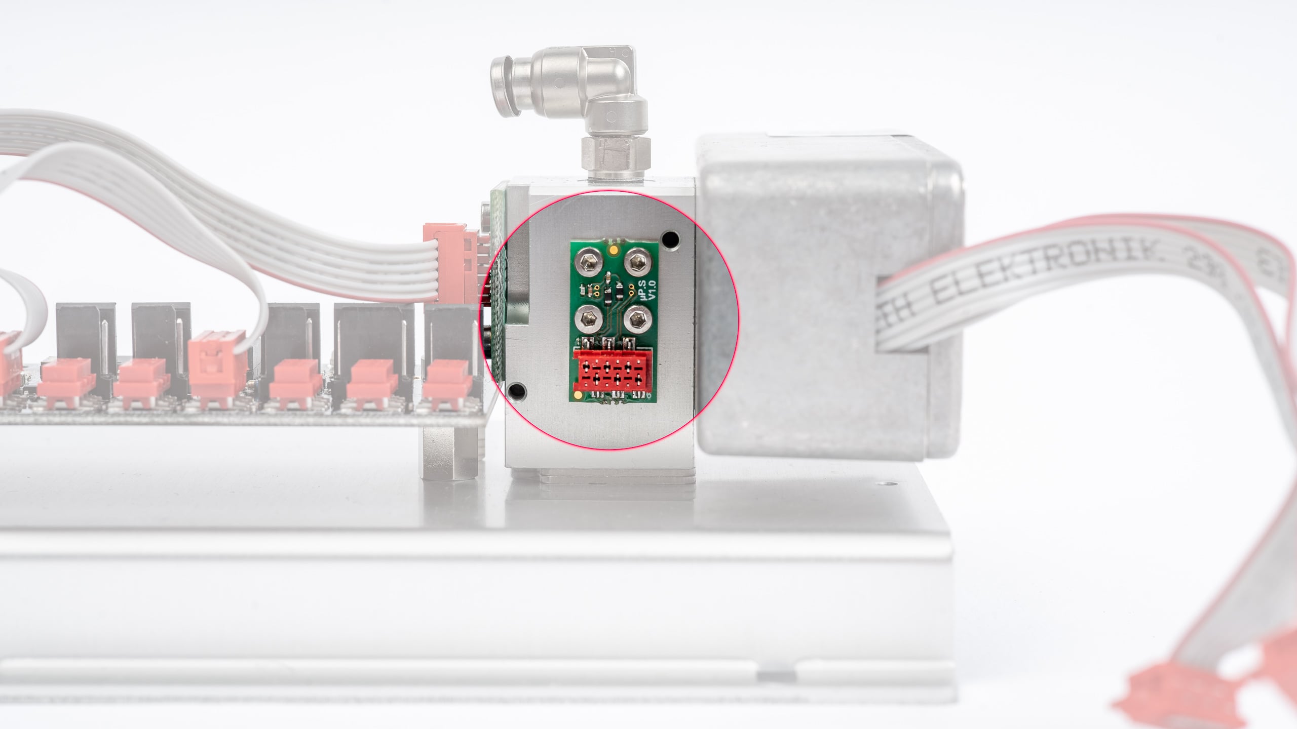
Overview
Specifications
Humidity Sensor
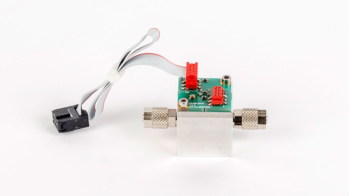
Overview
Specifications
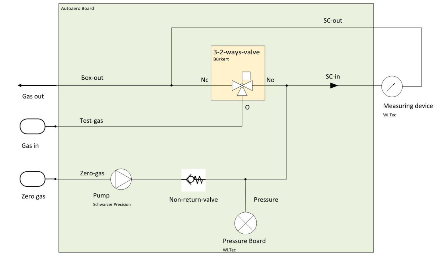
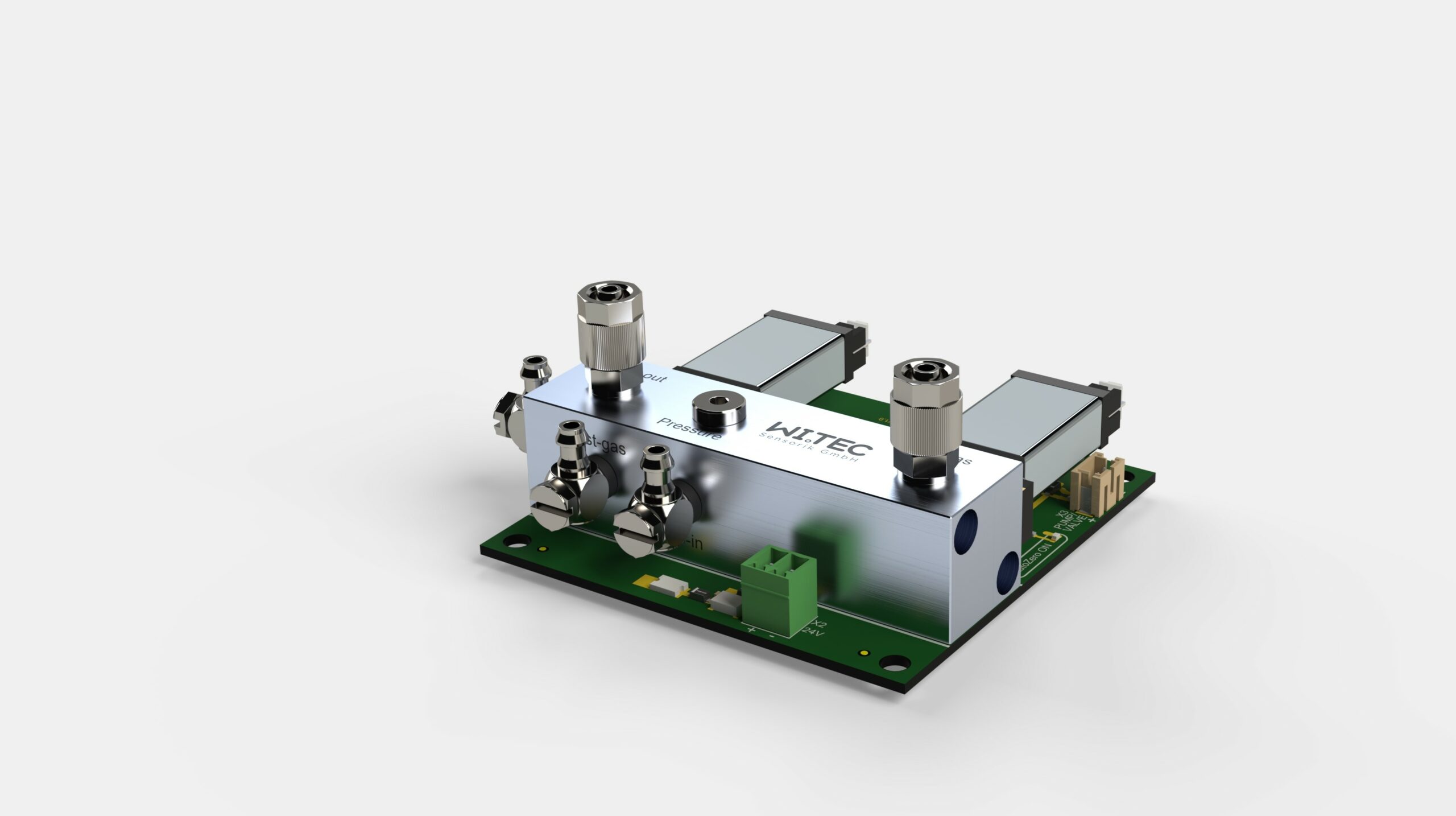
»MultiGas« Zero-point Adjustment Module (Air)
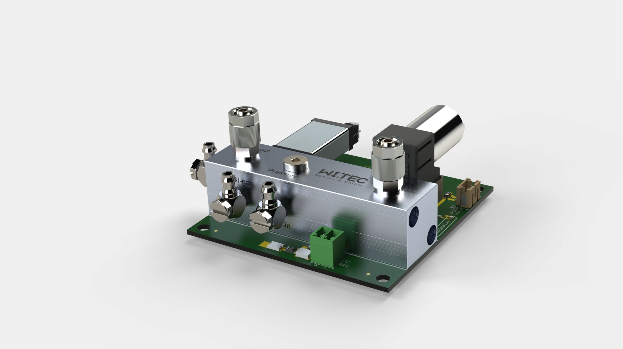
Overview
Features
Specifications
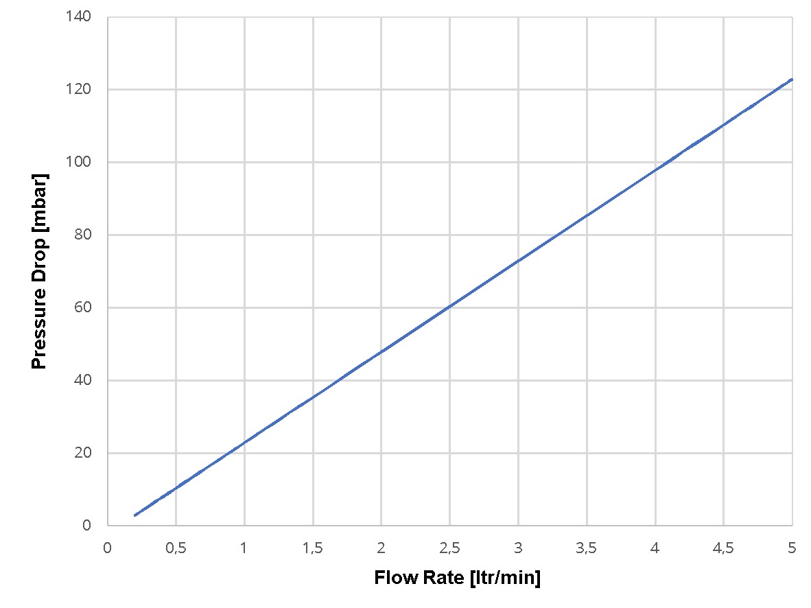
Pressure drop
Circuit diagram
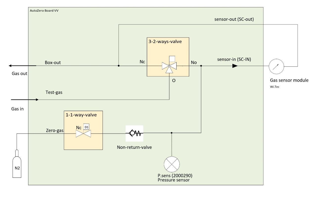
»MultiGas« Zero-point Adjustment Module (N2)
Overview
Features
Specifications
Pressure drop

Circuit diagram
Analog Voltage Output
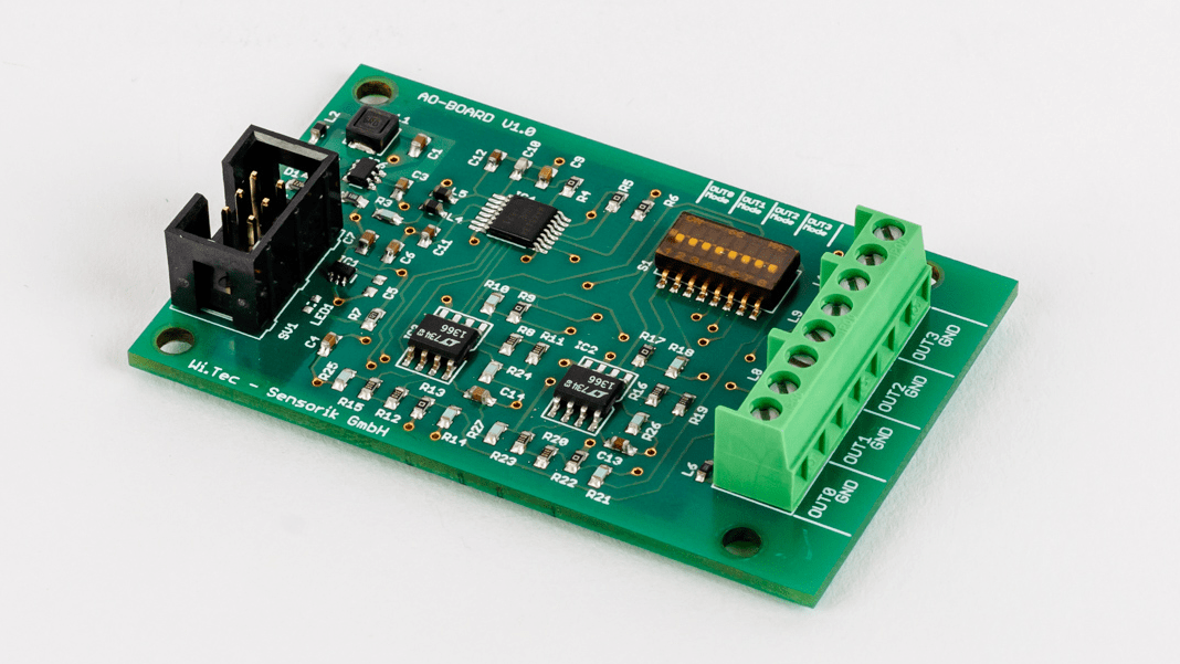
Overview
Technical Data


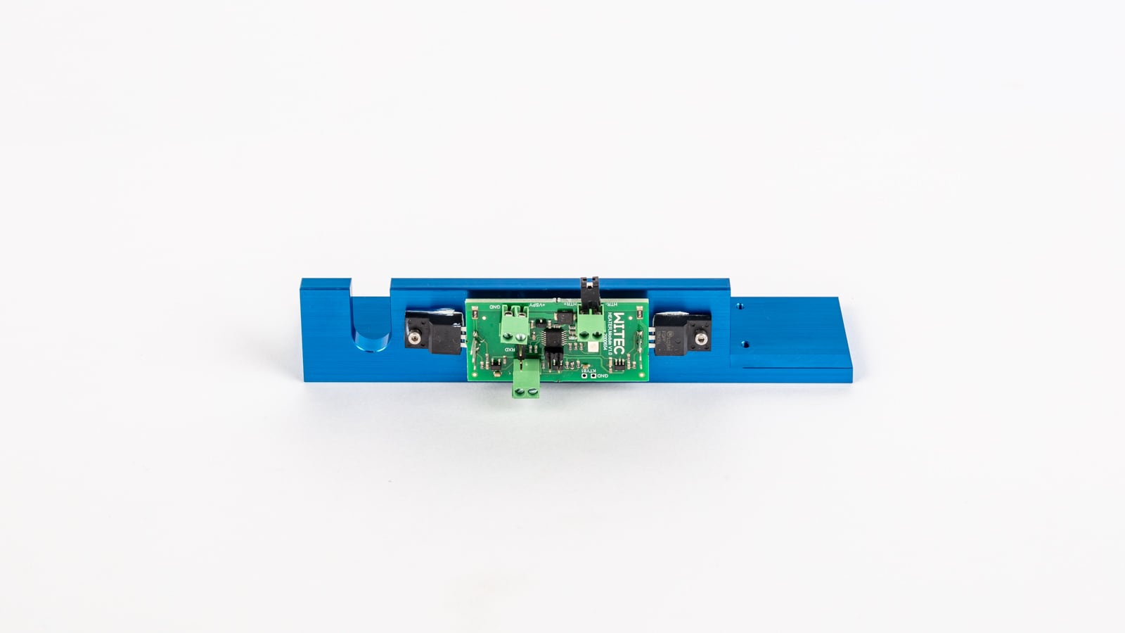
Contact No. Assignment to channel Wire Colors of provided Connection Cable 1 channel 1 white 2 channel 2 green 3 channel 3 yellow 4 channel 4 grey 5 ground brown Heating and Thermostatting of Sensor Casing
Overview
Features
Filter
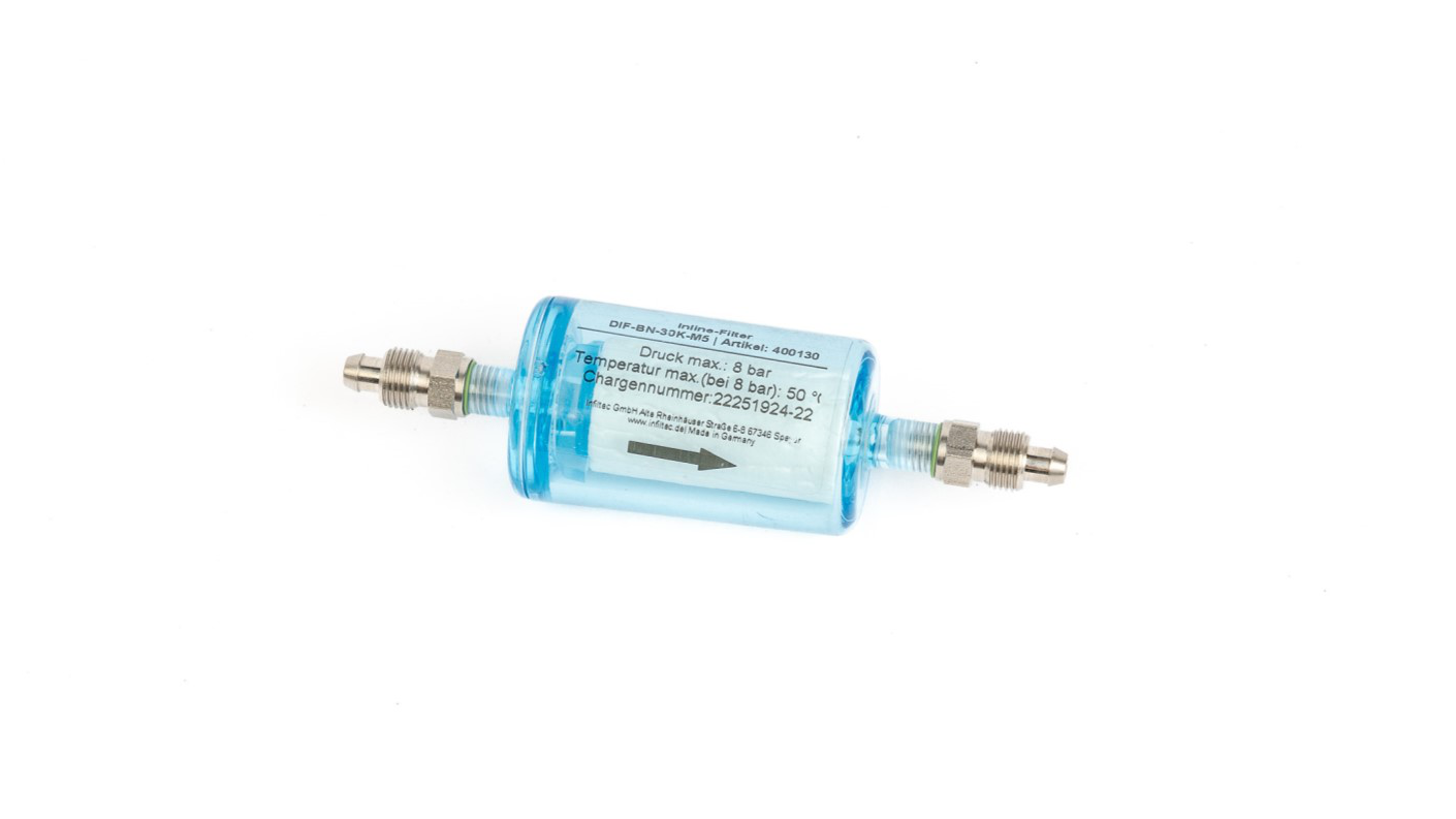
Overview
Description
Applications
Features
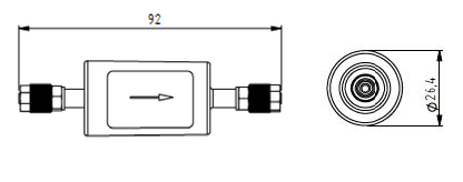
Dimensions
Specifications
General features
Dimensions Ø 26.4 mm x 92 mm Weight 26 g Tube connector 4/6 mm tube Flowrate 0 – 4 ltr/min Application Particle filter Housing volume 110 ml Medium contact materials Polyamide (housing), stainless steel (connector), FKM (O-ring) Exchange interval Depends on gas contamination Pressure drop (mbar) @ 1 ltr/min < 6 mbar Gas parameters
Operating temperature -5 °C – 60 °C Storage temperature -20 °C – 110 °C Max. pressure 8 bar Ambient humidity 0 – 95% rel. humidity (not condensing) 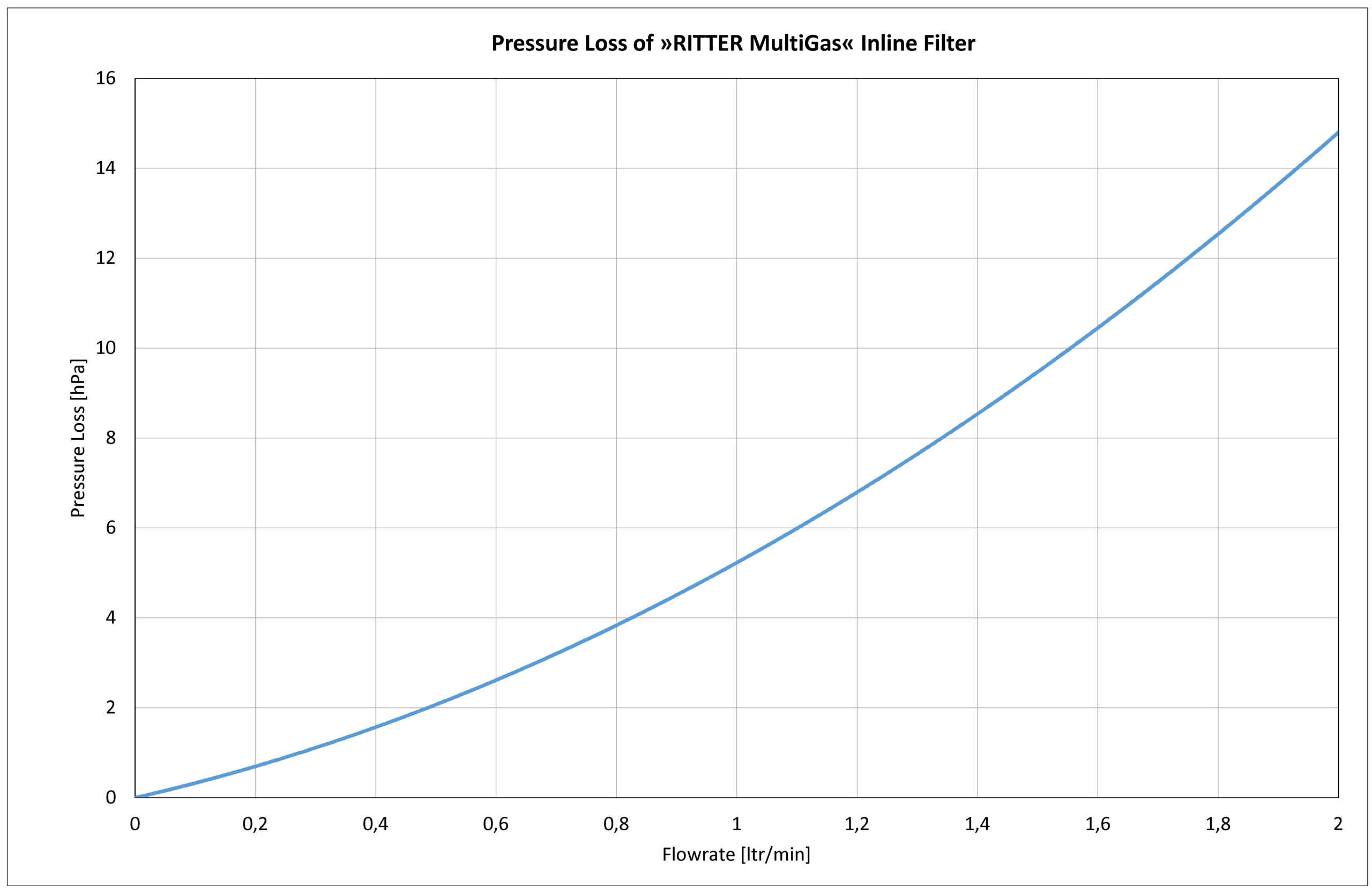
Sample Gas Pump

Overview
Applications
Features
Dimensions

Specifications
General features
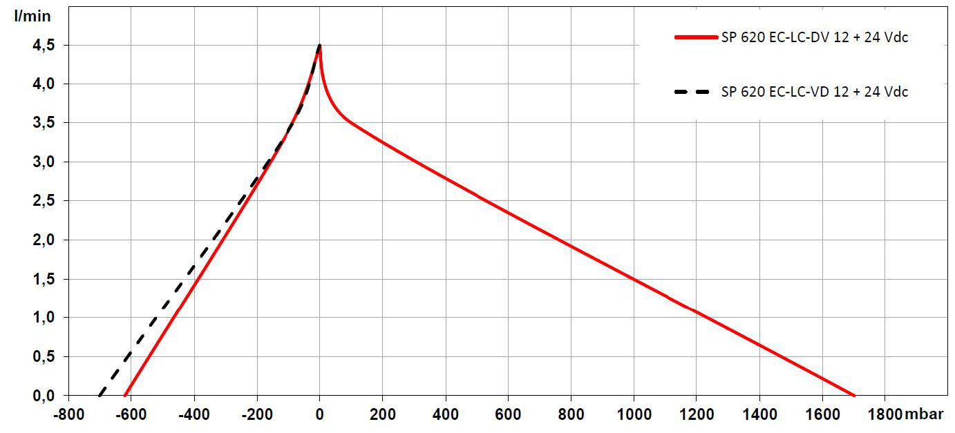
Operating voltage 24 VDC Max. nominal current 330 mA Pneumatic connector 4/6 mm tube Flow rate 0 – 4.5 ltr/min Max. pressure 1.7 bar Max. vacuum -620 mbar Medium contact materials PVDF (pump head)
PTFE (membrane)
FFKM (valve and seal)Weight 184 g Dimensions W x H x L 31 mm x 54 mm x 81.5 mm Gas parameters
Operating temperature 5 °C – 50 °C Storage temperature -20 °C – 60 °C Ambient humidity 0 – 95% rel. humidity (not condensing) Performance diagram
