- 1 Общие характеристики
- 1.1 Типы обсадных труб
- 1.2 Размеры & Технические характеристики
- 1.3 Назначение типов датчиков возможным комбинациям датчиков
- 1.3.1 Часть 1: Предварительно сконфигурированные датчики, включая тип корпуса 1
- 1.3.2 Часть 2: Предварительно сконфигурированные датчики, включая тип корпуса 2
- 1.3.3 Часть 3: Индивидуально комбинируемые сенсорные модули
- 1.3.4 Часть 4: Корпуса для сенсорных модулей
- 1.3.5 Часть 5: Встроенные опции
- 1.3.6 Часть 6: Аксессуары / Опции
- 1.4 Калибровки
- 1.5 Измерение влажных газов
- 2 Недостатки электрохимических (EC) датчиков по сравнению с оптическими датчиками RITTER »MultiGas« Sensors
- 3 Профилактические/защитные меры при измерении газов
- 4 Объем поставок
- 5 Настройка
- 6 Инфракрасные датчики
- 7 Ультрафиолетовые датчики
- 8 Опции (установлен внутри корпуса датчика)
Общие характеристики
Типы обсадных труб


Размеры & Технические характеристики
Тип корпуса 1 Тип корпуса 2 A 171 mm 444 mm B 290 mm (1) 305 mm C 86 mm 145 mm Вес, прибл. (2) 2+ kg 6,5 – 8 kg Подключения в/в/выход газа ПВДФ резьбовое соединение для трубки Øвнутри 4 mm, Øснаружи 6 mm Соединительная трубка PVC Rauclair Øвнутри 4 mm, Øснаружи 6 mm, 3 m Интерфейсы USB (стандарт), RS232 / CANbus / CANopen (опции), MODbus по запросу Электропитание 24 VDC, вкл. подключаемый блок питания
100 – 240 VAC, 50/60 Hz
(2) В зависимости от типа и количества встроенных модулей датчиков
Спецификации интерфейса
USB
- Тип: USB 2.0
- Разъем: Тип B
- Соединительный кабель: Тип B /
тип A
RS232
- Тип: RS232
- Разъем: D-sub9 женщина
- Соединительный кабель: D-sub9 1:1 штекер/штекер
CANopen
- Тип протокола: Режим CANopen 2
- Скорость передачи данных: 250 kBaud
- Node ID: 0x31
- Разъем: RJ45
CANbus
- Тип протокола: Режим CANbus 1 (нестандартный)
- Скорость передачи данных: 250 kBaud
- Идентификатор передачи: 0x208
- Идентификатор приема: 0x300
- Разъем: RJ45
MODbus
- Скорость передачи данных: 250 kBaud
- Databits: 8
- Stopbit: 1
- Parity: None
- Float Definition: IEE754
- Доступные регистры:
- Read Holding Register 0x03
- Read Input Register 0x04
- Write Single Register 0x06
- Разъем: RJ45
Назначение типов датчиков возможным комбинациям датчиков
Часть 1: Предварительно сконфигурированные датчики, включая тип корпуса 1
С арматурой для подключения газа, интерфейсом данных, подключаемым источником питания - готов к эксплуатации
Тип датчика:
RITTER MultiGas xxxСтатья
Нет.Группа газов
IRКоличество обнаруживаемых газов
в этой группеГруппа газов
UVКоличество обнаруживаемых газов
в этой группе xxx = mono IR1 2678 1 xxx = duo IR2 2742 2 xxx = trio IR3 2743 3 xxx = mono UV1 2749 1 xxx = mono UV1
Cl2 30%2763 1 xxx = duo UV2 2766 2 xxx = duo IR1 + UV1 2797 1 1 xxx = trio IR1 + UV2 na 1 2
Часть 2: Предварительно сконфигурированные датчики, включая тип корпуса 2
С арматурой для подключения газа, интерфейсом данных, подключаемым источником питания - готов к эксплуатации
Тип датчика:
RITTER MultiGas xxxСтатья
Нет.Группа газов
IRКоличество обнаруживаемых газов
в этой группеГруппа газов
UVКоличество обнаруживаемых газов
в этой группе xxx = mono UV1
H2S ≤ 5000 ppm2672 1 xxx = mono UV1
H2S ≤ 1%2855 1 xxx = UVRAS 2812 1 xxx = duo IR1
+ H2S ≤ 5000 ppm2959 1 1 xxx = duo IR1
+ (H2S ≤ 1% / NO)2960 1 1
Часть 3: Индивидуально комбинируемые сенсорные модули
Состав по спецификации заказчика, поставка включает корпус подходящего размера в соответствии с количеством и типом модулей - готов к использованию
Тип датчика:
RITTER MultiGas xxxСтатья
Нет.Группа газов
IRКоличество обнаруживаемых газов
в этой группеГруппа газов
UVКоличество обнаруживаемых газов
в этой группе xxx = Mod IR1 2813 1 xxx = Mod IR2 2814 2 xxx = Mod IR3 2815 3 xxx = Mod UV1 2830 1 xxx = Mod UV1
Cl2 30%na 1 xxx = Mod UV1
H2S ≤ 5000 ppm2841 1 xxx = Mod UV1
H2S ≤ 1%2856 1 xxx = Mod UV2 2831 2 xxx = Mod UVRAS 2917 3
Часть 4: Корпуса для сенсорных модулей
Сборка в соответствии со спецификацией заказчика
Тип корпуса:
RITTER MultiGasСтатья
Нет.Тип корпуса Подходит для xxx = Cas-2 (1) 2817 Тип корпуса 2 Несколько модулей до 444 x 305 x 145 mm xxx = Cas-3 (1) 2818 Тип корпуса 3 Несколько модулей до 444 x 305 x 189 mm
Часть 5: Встроенные опции
Тип опции:
RITTER MultiGasСтатья
No.Описание Диапазон измерения RMS-O2 (2) (3) 2795 Датчик кислорода 0 ‐ 25% RMS-O2 (2) (3) 2767 Датчик кислорода 0 – 100% RMS-O2-resist (3) 2824 Датчик кислорода
H2S устойчивый0,5 – 35% RMS-P (2) (3) 2771 Датчик давления 800 – 1200 mbar абс.
Разрешение <1 mbar RMS-P-resist (3) 2825 Датчик давления
H2S устойчивый0,2 – 3,5 bar абс.
Разрешение 2 mbar RMS-H (2) (3) 2773 Датчик влажности 0 – 100% RH RMS-A/O 2648 Аналоговый выход напряжения
0-2 V / 0-5 V / 0-10 V4 порта аналогового выхода для 4 отдельных концентраций газа
16 bit RMS‐CasHeat 2954 Термостатированный корпус Нагрев и термостатирование корпуса датчика при температуре 45 °C
(3) Доступен только в качестве дополнения к ИК- или УФ-датчику
Часть 6: Аксессуары / Опции
Тип опции:
RITTER MultiGas xxxСтатья
No.Описание Диапазон измерения xxx = Cal-ZP-N2 2805 Калибровочный газ N2 Для калибровки всех газов по нулевой точке xxx = Flow-V 2806 Мини-клапан потока Контроль расхода для баллона с калибровочным газом
Вкл. манометр xxx = Cal-CG-Cat1 2948 Калибровка с помощью специального газа-носителя (Ar, H2, He)
для газов категории 1Газы категории 1:
xxx = Cal-CG-Cat2 2949 Калибровка с помощью специального газа-носителя (Ar, H2, He)
для газов категории 2Газы категории 2:
xxx = Cal-ReCal-Cat1 2950 Повторная калибровка для газов категории 1 Газы категории 1:
xxx = Cal-ReCal-Cat2 2951 Повторная калибровка для газов категории 2 Газы категории 2:
Infrared module NDIR Ультрафиолетовый модуль NDUV
Калибровки
В зависимости от количества анализируемых газов необходимо выбрать подходящий калибровочный газ. Кроме того, тип газа также влияет на выбор оптимального калибровочного газа. Из-за почти бесконечного числа возможных комбинаций следующий список следует воспринимать только как первый обзор.
Измерение влажных газов
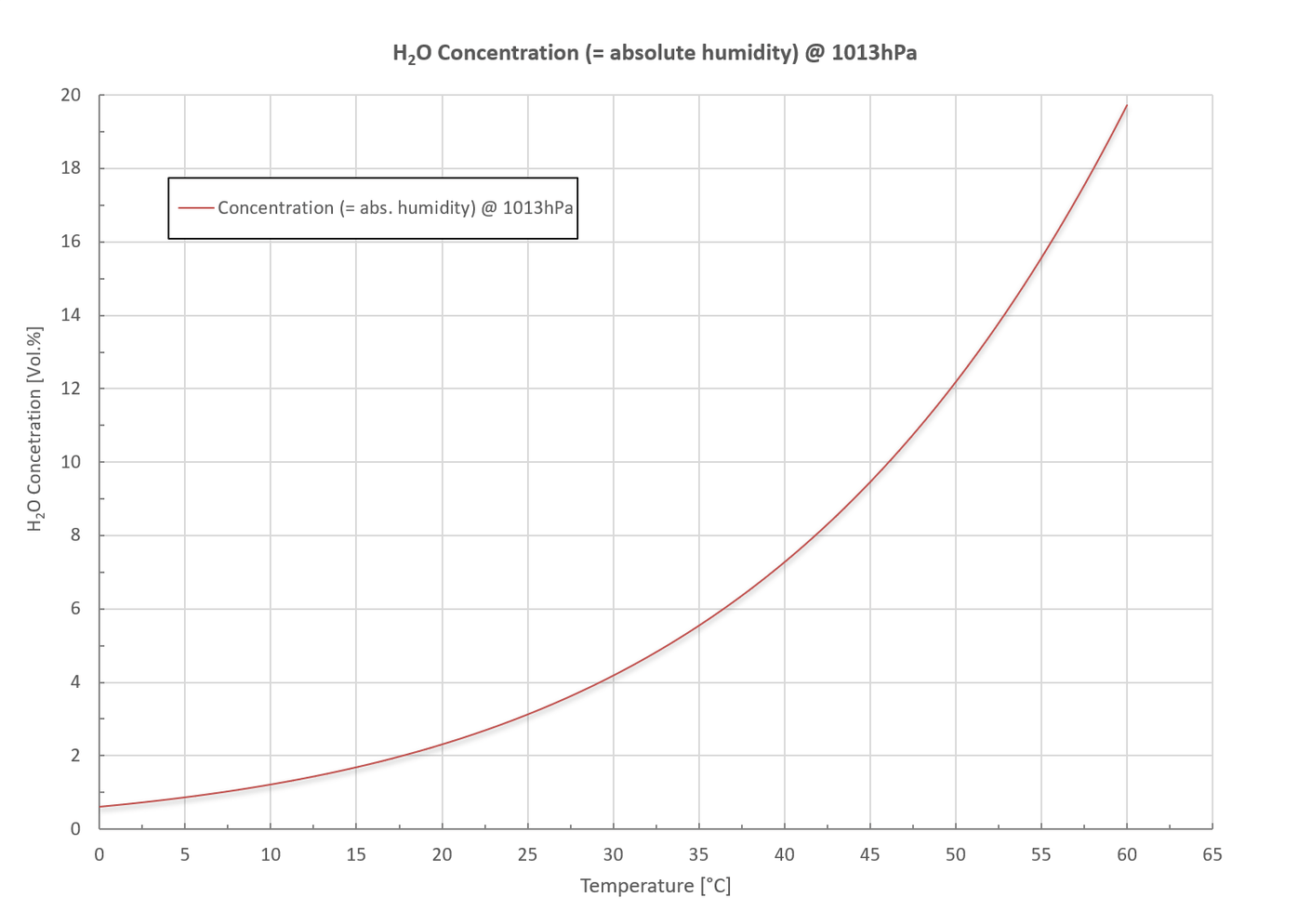
При измерении влажных газов необходимо предотвратить конденсацию водяного пара внутри датчика. На следующей диаграмме показана максимальная концентрация водяного пара (= абсолютная влажность) в объемных % в зависимости от температуры при стандартном давлении 1013 мбар.
На диаграмме показано:
Конденсат можно предотвратить с помощью следующих мер:
С помощью опционального датчика влажности можно измерять относительную влажность в диапазоне измерений 0 ~ 100% отн. вл. Кроме того, можно измерять и абсолютную влажность в г/м³. Оба значения отображаются в поставляемом программном обеспечении.
Недостатки электрохимических (EC) датчиков по сравнению с оптическими датчиками RITTER »MultiGas« Sensors
Профилактические/защитные меры при измерении газов
Важно: Пожалуйста, укажите желаемые опции при заказе
a) Дополнительное трубное соединение для промывки корпуса
Газопроводы внутри корпуса и измерительная кювета газонепроницаемы благодаря уплотнительным кольцам и другим газонепроницаемым соединениям. Однако, как и в случае со всеми соединениями, нельзя исключить утечку, пусть даже незначительную. С помощью дополнительного соединения трубки для промывки корпуса можно предотвратить скопление измерительного газа внутри корпуса.
В случае токсичных или агрессивных газов, через это трубное соединение может быть подключен всасывающий трубопровод, который создает пониженное давление внутри корпуса, предотвращая тем самым выход газа из корпуса.
В случае непригодных газов (метан, водород и т.д.), через это трубное соединение может быть подключен напорный или всасывающий трубопровод, создающий избыточное или пониженное давление внутри корпуса, что предотвращает накопление воспламеняющейся газовой смеси.
Пожалуйста, обрати внимание: H2S может восприниматься как неприятный запах даже в диапазоне ppb. Даже при кольцевом уплотнении могут возникать микроутечки, которые можно устранить путем промывки корпуса.
b) Обогреваемый и термостатируемый корпус
Необходимо предотвратить конденсацию измерительного газа внутри датчика. Как правило, этого можно достичь с помощью конденсатоотводчика или газоохладителя. См. также раздел »Измерение влажных газов«. В качестве альтернативы внутренний корпус датчика может быть нагрет и термостатирован на 45 °C (стандарт). Подогрев не только позволяет избежать конденсации влаги внутри датчика, но и обеспечивает постоянство результатов измерений. См. раздел »Нагрев и термостатирование корпуса датчика«.
c) Фильтр частиц
Пожалуйста, убедитесь с помощью подходящего фильтра, что в датчик не попали частицы. Они могут заблокировать маленькие отверстия внутренней арматуры. Рекомендуется использовать фильтры размером 5 микрон или меньше.
Объем поставок
| Количество предметов | Пункт |
|---|---|
| 1 | Папка с документами, включая: Сертификат калибровки / Листы данных / Руководство по программному обеспечению |
| 1 | Датчик в настольном корпусе |
| 1 | Подключаемый блок питания Вход: 100 – 240 V-AC, 50/60 Hz, 0.4 A Выход: 24 V-DC, 0,5 A, 12 Вт или 36 Вт (H2S / Датчик UVRAS) |
| 1 | Программное обеспечение для сбора данных (на карте памяти USB) |
| 1 | Соединительный кабель: Датчик → PC стандартная: USB V2.0 A/B, 1 m Вариант: RS232, 3m |
| 3m | Витоновые трубки Øвнутри 4mm / Øснаружи 6mm |
Настройка
- Тщательно распакуйте все предметы.
- Установите программное обеспечение для сбора данных в соответствии с »RITTER MultiGas Software Manual«.
Не запускайте программу в этот момент. - Размещение датчика:
- Если датчик используется в сочетании с MilliGascounter RITTER, датчик должен быть расположен (по направлению потока) перед MilliGascounter, если этот MilliGascounter заполнен раствором HCl. В противном случае датчик может быть поврежден парами HCl, выходящими из MilliGascounter.
- Поместите датчик рядом с источником газа.
Пожалуйста, обрати внимание: Как можно более короткое трубное соединение между источником газа и датчиками позволяет создать небольшое мертвое пространство в трубке. В свою очередь, небольшое мертвое пространство обеспечивает быстрое время отклика датчика.
- Подключите адаптер питания к разъему »DC 24 В« на задней стороне датчика и к сети.
- Подключите кабель сбора данных к соответствующему разъему на задней стороне датчика и к компьютеру:
- USB-кабель к розетке »USB«
- Кабель RS232 к розетке »RS 232« (Опция)
- Подключите источник газа к впускному отверстию датчика с помощью прилагаемой трубки следующим образом:
- Снимите винтовые крышки, а также красные резиновые колпачки транспортного замка с впуска и выпуска газа.
- Наденьте резьбовую крышку на конец трубки впуска газа так, чтобы резьба крышки была обращена к концу трубки.
- Наденьте трубку на конус в центре отверстия для впуска газа.
- Наденьте резьбовую крышку на входное отверстие для газа и закрутите ее от руки.
- Если применимо: Подсоедините газовыпускной порт датчика к другим компонентам, таким как мешки для отбора проб газа, выпускные трубки и т.д. Подключение трубки к порту выхода газа происходит аналогично описанному выше.
- Включите выключатель питания на передней стороне корпуса датчика.
- Запустите программное обеспечение и откройте COM-порт(ы) подключенного(ых) модуля(ов) датчиков в соответствии с руководством к программному обеспечению.
Датчик RITTER »MultiGas« теперь готов к использованию.
Инфракрасные датчики
»MultiGas« Инфракрасный модуль NDIR
Описание
Газовый анализ на основе NDIR-метода является признанным методом определения концентрации газов в сложных смесях. В датчиках RITTER »MultiGas« используются новые оптические компоненты для достижения оптимальных результатов анализа: До 3 оптических фильтров анализируют газ, проходящий через датчик, как один газовый поток. Дополнительные датчики кислорода, давления и влажности работают в одном потоке газа.
Отдельные внутренние модули герметизированы с помощью кольцевых соединений.
Для достижения оптимальной адаптации к требуемому диапазону измерений длина модульных измерительных ячеек (= кювет) может быть реализована в диапазоне от 5 мм (большой диапазон измерений в процентах) до 250 мм (малый диапазон измерений в промилле).
Кюветы длиной ≥ 20 мм покрыты стойким слоем золота, чтобы улучшить отражающие свойства для определения низких концентраций и обеспечить дополнительную защиту от слабоагрессивных газов. Кюветы, используемые с агрессивными газами, также покрыты золотом.
Другие внутренние механические детали изготовлены из алюминия, опционально из нержавеющей стали.
Для приложений с быстрой реакцией измерительная система обеспечивает стабильный результат в течение t90 ≈ 3 секунд.
Весь блок может быть разобран для удобства обслуживания/сервиса.
Приложения
Технические характеристики
Общие характеристики
| Измерительная техника: | Инновационный NDIR-датчик (недисперсионный инфракрасный датчик) |
| Обнаруживаемые газы: | CO2 CO N2O CnHm CH4 CF4 SF6 H2O |
| Количество одновременно обнаруживаемых газов: | макс. 3 на блок датчика |
| Диапазоны измерений: | См. Таблица диапазонов измерений |
| Диапазон расхода воздуха: | 5 ~ 300 ltr/h При больших расходах датчик может работать в режиме байпаса |
| Макс. давление газа на входе: | 300 mbar |
| Потеря давления (без дополнительных опциональных датчиков): | 10 @ 100 / 35 @ 200 / 70 @ 300 (mbar @ ltr/h) |
| Температурная компенсация: | Да |
| Программное обеспечение для сбора данных: | Да |
| Срок службы источника ИК-излучения: | > 40 000 h |
| Мерная чаша: | Алюминиевые, с диапазонами измерения ≤1%, позолоченные внутри |
| Герметизация кюветы: | Витоновое уплотнительное кольцо |
| кожух: | Высококачественный корпус столешницы, алюминий |
| Размеры (W x H x L): | 171 x 86 x 290 mm |
| Вес: | примерно 2 kg |
| Газовые соединения: | ПВДФ резьбовое соединение для трубок Øвнутри 4 мм, Øза пределами 6 мм |
Данные измерений
| Ошибка линейности: | < ± 1% F.S. |
| Повторяемость: | ± 0,5% F.S. |
| Долгосрочная стабильность нулевая: | < ± 2% F.S. / неделя |
| Долгосрочный диапазон стабильности: | < ± 2% F.S. / месяц |
| Влияние температуры на нулевую точку: | < 1% F.S. / 10K |
| Влияние температуры на пролет: | < 2% F.S. / 10K |
| Перекрестная чувствительность: | < 2% F.S. |
| Влияние давления: | < 1.5% / 10hPa от измеренного значения |
| Время разминки: | 2 min |
| Время отклика (t90): | ≈ 3 sec |
| Частота дискретизации с помощью программного обеспечения: | ≤ 10 Hz |
| Предел обнаружения: | См. Таблица пределов обнаружения |
| Разрешение: | 0,5 x предел обнаружения |
| Водяной пар: | Нет влияния на измерения CO2 и CH4 |
Электрические характеристики
| Электропитание: | 24 VDC вкл. вилку питания 100 ~ 240 VAC 50/60 Hz: 24 VDC |
| Средняя потребляемая мощность: | < 1W |
| Интерфейс: | USB (стандарт), RS232 / CANbus / CANopen (опции) вкл. кабель передачи данных 1 м |
| Аналоговый выход напряжения (Опция): | 0 – 2 V / 0 – 5 V / 0 – 10 V |
Параметры газа
| Рабочая температура: | +15 ~ +45 °C |
| Температура хранения: | –20 ~ +60 °C |
| Рабочее давление: | 800 ~ 1200 hPa (mbar) |
| Влажность окружающей среды: | 0 ~ 95% относительная влажность Необходимо предотвратить образование конденсата внутри датчика! |
* Анализ CnHm: Калибровка датчиков для CnHm будет проводиться с пропаном. Ароматические углеводороды также измеряются, но с другим весовым коэффициентом. Это означает, что чувствительность сенсора к этим газам значительно меньше, чем к другим углеводородам.
Список стандартных диапазонов измерений *1 ( и пределы обнаружения *2 )
| Стандартные диапазоны измерений с соответствующими пределами обнаружения ( % от F.S. *3 ) | ||||||||||||||||
|---|---|---|---|---|---|---|---|---|---|---|---|---|---|---|---|---|
| 100 Vol.% | 50 Vol.% | 30 Vol.% | 20 Vol.% | 10 Vol.% | 5 Vol.% | 1 Vol.% | 5.000 ppm | 2.000 ppm | 1.000 ppm | 500 ppm | 300 ppm | 100 ppm | 50 ppm | 10 ppm | 1 ppm | |
| CO2 | (< 0,1%) | (< 0,1%) | (< 0,1%) | (< 0,1%) | (< 0,1%) | (< 0,1%) | (< 0,1%) | (< 0,1%) | (< 0,1%) | (< 0,1%) | (< 0,3%) | (< 0,3%) | ||||
| CO | (< 0,2%) | (< 0,2%) | (< 0,2%) | (< 0,2%) | (< 0,2%) | (< 0,2%) | (< 0,2%) | (< 0,3%) | (< 0,5%) | (< 0,5%) | ||||||
| N2O | (< 0,1%) | (< 0,1%) | (< 0,1%) | (< 0,1%) | (< 0,1%) | (< 0,1%) | (< 0,1%) | (< 0,3%) | ||||||||
| CnHm*4 | (< 0,1%) | (< 0,1%) | (< 0,1%) | (< 0,2%) | (< 0,2%) | (< 0,2%) | (< 0,2%) | (< 0,5%) | (< 0,5%) | |||||||
| CH4 | (< 0,1%) | (< 0,1%) | (< 0,1%) | (< 0,1%) | (< 0,1%) | (< 0,1%) | (< 0,1%) | (< 0,3%) | (< 0,5%) | |||||||
| CF4 | (< 0,2%) | (< 0,2%) | (< 0,2%) | (< 0,02%) | (< 0,05%) | |||||||||||
| SF6 | (< 0,1%) | (< 0,1%) | (< 0,1%) | (< 0,2%) | (< 0,5%) | (< 0,3%) | (< 0,3%) | |||||||||
| H2O | ||||||||||||||||
Infrared module NDIR Ультрафиолетовый модуль NDUV
Определение предела обнаружения
Предел обнаружения - это наименьшее значение измерения, которое может быть получено с определенной неопределенностью. Эта неопределенность включает в себя разрешение, шум и стабильность газового датчика для конкретного газа и конкретного диапазона измерений. Для оценки значения предела обнаружения проводится несколько единичных измерений при одинаковых условиях измерения. По полученным результатам единичных измерений рассчитывается стандартное отклонение »Sigma« (σ). Значения, приведенные в таблице, равны тройной величине "Sigma".
Перекалибровки
Для ИК-датчиков рекомендуются следующие интервалы повторной калибровки:
Ультрафиолетовые датчики
УФ-датчик RITTER »MultiGas« - это первый в мире газоаналитический модуль на основе миниатюрных УФ-светодиодов. Стабильность и срок службы этих УФ-светодиодов позволяет проводить высокоточный анализ газов вплоть до диапазона ppm. Благодаря использованию двух УФ-светодиодов можно одновременно определять два газа. Кроме того, при таком подходе можно реализовать диапазон измерений от ppm до об.-%. В спектральном диапазоне от 200 нм до 500 нм с помощью новой сенсорной платформы можно надежно обнаружить оксиды азота (NO + NO2), ароматические углеводороды, сероводород, озон, диоксид серы и хлор. Весь блок может быть разобран для удобства обслуживания/сервиса. Отдельные внутренние модули герметизированы с помощью кольцевых соединений. Для достижения оптимальной адаптации к требуемому диапазону измерений длина модульных измерительных ячеек (= кювет) может быть реализована в диапазоне от 5 мм (большой диапазон измерений в процентах) до 250 мм (малый диапазон измерений в промилле). Кюветы длиной ≥ 20 мм покрыты стойким слоем золота для улучшения отражающих свойств при определении низкого уровня концентрации. Кюветы, используемые с агрессивными газами, также покрыты золотом. Внутренние механические детали изготовлены из алюминия, опционально из нержавеющей стали. Для приложений с быстрой реакцией измерительная система обеспечивает стабильный результат в течение t90 ≈ 1-2 секунды. Infrared module NDIR Ультрафиолетовый модуль NDUV Определение предела обнаружения Предел обнаружения - это наименьшее значение измерения, которое может быть получено с определенной неопределенностью. Эта неопределенность включает в себя разрешение, шум и стабильность газового датчика для конкретного газа и конкретного диапазона измерений. Для оценки значения предела обнаружения проводится несколько единичных измерений при одинаковых условиях измерения. По полученным результатам единичных измерений рассчитывается стандартное отклонение »Sigma« (σ). Значения, приведенные в таблице, равны тройной величине "Sigma". Для УФ-датчиков рекомендуются следующие интервалы повторной калибровки: Для обнаружения NO используется EDL (безэлектродная газоразрядная лампа). В EDL N2 и O2 преобразуются в NO и создают селективное УФ-излучение. С помощью этого излучения становится возможным измерение NO без перекрестной чувствительности. Этот метод называется УФ-резонансной абсорбционной спектроскопией (UVRAS). Комбинация технологий UVRAS и NDUV позволяет одновременно анализировать NO, NO2 и SO2 в нижнем диапазоне ppm, что особенно важно при анализе дымовых газов (непрерывный мониторинг выбросов, CEM). Infrared module NDIR Ультрафиолетовый модуль NDUV Определение предела обнаружения Предел обнаружения - это наименьшее значение измерения, которое может быть получено с определенной неопределенностью. Эта неопределенность включает в себя разрешение, шум и стабильность газового датчика для конкретного газа и конкретного диапазона измерений. Для оценки значения предела обнаружения проводится несколько единичных измерений при одинаковых условиях измерения. По полученным результатам единичных измерений рассчитывается стандартное отклонение »Sigma« (σ). Значения, приведенные в таблице, равны тройной величине "Sigma". Для УФ-датчиков рекомендуются следующие интервалы повторной калибровки: Датчик H2S работает по принципу недисперсионного УФ-поглощения (NDUV). Используемая длина волны измерения находится в нижнем нанометровом диапазоне, что позволяет проводить измерения без помех для водяного пара и углеводородов. Это делает датчик идеальным для использования в измерениях биогаза, поскольку сопутствующие газы, такие как NH3, CO2, CH4 и H2O не влияют на точность измерений. В отличие от фотометрических датчиков NDUV сроки службы электрохимических датчиков для измерения H2S ограничены. Обратите внимание, что данные о сроке службы таких датчиков приведены для воздуха, а не для измерения H2S. Для концентраций H2S > 200 ppm срок службы уменьшается, для концентраций > 1000 ppm - критический. В то время как измерительные характеристики УФ-светодиодов остаются постоянными, датчики EC становятся »глухими«. Infrared module NDIR Ультрафиолетовый модуль NDUV Определение предела обнаружения Предел обнаружения - это наименьшее значение измерения, которое может быть получено с определенной неопределенностью. Эта неопределенность включает в себя разрешение, шум и стабильность газового датчика для конкретного газа и конкретного диапазона измерений. Для оценки значения предела обнаружения проводится несколько единичных измерений при одинаковых условиях измерения. По полученным результатам единичных измерений рассчитывается стандартное отклонение »Sigma« (σ). Значения, приведенные в таблице, равны тройной величине "Sigma". Для УФ-датчиков рекомендуются следующие интервалы повторной калибровки: Датчик кислорода поставляется только в качестве дополнительного сенсорного модуля к датчикам RITTER »MultiGas« NDIR или NDUV. Измеренная концентрация кислорода отображается в прилагаемом программном обеспечении. Датчик встроен в корпус датчиков RITTER »MultiGas«. Доступны следующие версии: * связанный с Pa = 1013 hPa, Ta = 25 °C, RH = 50%, поток = 2,5 l/min Изменение давления газа и/или атмосферного давления вызывает изменение количества молекул в объеме и, следовательно, изменение плотности газа. Это изменение плотности, в свою очередь, оказывает значительное влияние на результат измерения концентрации датчиком. Измеряя давление газа внутри ячейки для образца (кюветы), значение измерения концентрации компенсируется/корректируется. Датчик давления позволяет увеличить точность измерения газоанализа в 15 раз: Датчик давления всегда встроен в датчики RITTER »MultiGas« NDIR в качестве микросенсора. Для датчиков NDUV он поставляется опционально и встраивается в корпус датчика. Измеренное значение давления отображается в прилагаемом программном обеспечении. Для неагрессивных газов: Для H2S и аналогичных кислых газов: Датчик влажности поставляется только в качестве дополнительного сенсорного модуля к датчикам RITTER »MultiGas« NDIR или NDUV. Датчик встроен в корпус датчиков RITTER »MultiGas«. Измеренные значения влажности (абсолютной и относительной) отображаются в прилагаемом программном обеспечении. Модуль вывода аналогового напряжения позволяет одновременно выводить до 4 различных значений на 4 отдельных канала: Для подключения к аналоговому устройству сбора данных выходной порт аналогового напряжения альтернативно обеспечивает следующие уровни напряжения: Диапазон напряжения предварительно устанавливается в соответствии с заказом и не может быть изменен пользователем. Обратите внимание на назначение соответствующих измерений концентрации газа соответствующим каналам. Эти назначения указаны в протоколе калибровки блока датчика. Назначение контактов каналам измерения концентрации газа на разъеме и вилке аналогового выхода напряжения: Аналоговые выходные сигналы датчиков кислорода и влажности: В альтернативном режиме может передаваться только один из этих двух сигналов. Соединительный кабель поставляется с открытыми проводами для подключения к аналоговому устройству сбора данных пользователя. Цвета проводов указаны в таблице выше. Для того чтобы избежать конденсации влажного газа внутри датчика, датчик и корпус датчика могут быть нагреты и термостатированы. По умолчанию терморегулятор настроен на 45 °C; по запросу возможны более низкие температуры. Нагревательный элемент и регулятор температуры устанавливаются на опоре измерительной кюветы. Фильтр для частиц газа поставляется в качестве аксессуара для тех случаев, когда пользователь не проводит дополнительную фильтрацию газа. Он выполнен в виде линейного фильтра, который легко вставляется в газовую трубку перед всеми датчиками RITTER »MultiGas«. Пожалуйста, обрати внимание: Важно, чтобы частицы не попадали внутрь датчика, так как это приведет к блокировке маленьких отверстий внутри датчика. Каждый датчик поставляется с одним фильтром на газовую линию. Фильтр вставляется в трубку подачи с помощью резьбового соединения. Дополнительные фильтры можно заказать у вашего национального партнера по дистрибуции RITTER. MultiGas Ультрафиолетовый модуль NDUV
Описание
Приложения
Технические характеристики
Общие характеристики
Измерительная техника: Инновационный датчик NDUV
(недисперсионный ультрафиолетовый датчик)Обнаруживаемые газы: Количество одновременно обнаруживаемых газов: max. 2 Диапазоны измерений: См. Таблица диапазонов измерений Диапазон расхода воздуха: 5 ~ 300 ltr/h
При больших расходах датчик может работать в режиме байпасаМакс. давление газа на входе: 300 mbar Потеря давления (без дополнительных опциональных датчиков): 10 @ 100 / 35 @ 200 / 70 @ 300 (mbar @ ltr/h) Температурная компенсация: Да Программное обеспечение для сбора данных: Да Срок службы источника ультрафиолетового излучения: > 8 000 h Мерная чаша: Нержавеющая сталь с силиконовым покрытием внутри Герметизация кюветы: Витоновое уплотнительное кольцо Внутренние трубки: FKM / Viton (фторированный каучук) кожух: Высококачественный корпус столешницы, алюминий Размеры (Ширина x Высота x Длина): 464 x 189 x 305 mm Вес: примерно 6,5+ kg Газовые соединения: ПВДФ резьбовое соединение для трубок Øвнутри 4 мм, Øза пределами 6 мм Данные измерений
Ошибка линейности: < ± 1% F.S. Повторяемость: ± 0,5% F.S. Долгосрочная стабильность нулевая: < ± 1% F.S. / 24 h Долгосрочный диапазон стабильности: < ± 1% F.S. / month Влияние температуры на нулевую точку: < 1% F.S. / 10K Влияние температуры на пролет: < 2% F.S. / 10K Перекрестная чувствительность: < 2% F.S. Влияние давления: < 1.5% / 10 hPa от измеренного значения Время разминки: 1 min (первоначальный), < 60 min для получения полной спецификации Время отклика (t90): 1.5 – 15 sec Частота дискретизации с помощью программного обеспечения: ≤ 10 Hz Предел обнаружения: См. Таблица диапазонов измерений Разрешение: 0,5 x предел обнаружения Электрические характеристики
Электропитание: 24 VDC вкл. вилку питания 100 ~ 240 VAC
50/60 Hz: 24 VDC Ток питания (пик) < 0.4 A Средняя потребляемая мощность < 7,5 W Интерфейс: USB (стандарт)
RS232 / CANbus / CANopen (опции)
вкл. кабель передачи данных 1 м Аналоговый выход напряжения (Опция): 0-2 V / 0-5 V / 0-10 V Параметры газа
Рабочая температура: +25 ~ +45 °C Температура хранения: –20 ~ +60 °C Рабочее давление: 800 ~ 1200 hPa (mbar) Влажность окружающей среды: 0 ~ 95% относительная влажность
Необходимо предотвратить образование конденсата внутри датчика!Список стандартных диапазонов измерений *1 ( и пределы обнаружения *2 )
Стандартные диапазоны измерений с соответствующими пределами обнаружения ( % от F.S. *3 ) 100
Vol.%50
Vol.%30
Vol.%20
Vol.%10
Vol.%5
Vol.%1
Vol.%5.000
ppm2.000
ppm1.000
ppm500
ppm300
ppm100
ppm50
ppm10
ppm1
ppm O3
(< 0,1%)
(< 0,1%)
(< 0,1%)
(< 0,2%)
(< 0,5%)
(< 0,5%)
(< 0,5%) CL2
(< 0,1%)
(< 0,1%)
(< 0,1%)
(< 0,1%)
(< 0,1%)
(< 0,1%)
(< 0,1%)
(< 0,2%)
(< 0,5%) SO2
(< 0,1%)
(< 0,1%)
(< 0,1%)
(< 0,1%)
(< 0,1%)
(< 0,1%)
(< 0,1%)
(< 0,1%)
(< 0,5%)
(< 0,5%)
(< 0,5%) H2S
(< 0,1%)
(< 0,1%)
(< 0,1%)
(< 0,1%)
(< 0,2%)
(< 0,5%) NO2
(< 0,1%)
(< 0,1%)
(< 0,1%)
(< 0,2%)
(< 0,2%)
(< 0,5%)
(< 0,5%)
(< 0,5%) NO
(< 0,1%)
(< 0,1%)
(< 0,1%)
(< 0,2%)
(< 0,2%) Перекалибровки
MultiGas Ультрафиолетовый модуль NDUV / UVRAS
Описание
Приложения
Технические характеристики
Общие характеристики
Измерительная техника: Ультрафиолетовая резонансная абсорбционная спектроскопия (UVRAS) Обнаруживаемые газы: Количество одновременно обнаруживаемых газов: макс. 3 на блок датчика Диапазоны измерений: См. Таблица диапазонов измерений Диапазон расхода воздуха: 5 ~ 300 ltr/h
При больших расходах датчик может работать в режиме байпасаМакс. давление газа на входе: 300 mbar Потеря давления (без дополнительных опциональных датчиков): 10 @ 100 / 35 @ 200 / 70 @ 300 (mbar @ ltr/h) Дополнительный обогреваемый и термостатируемый корпус внутри корпуса датчика: Да Температурная компенсация: Да Программное обеспечение для сбора данных: Да Срок службы источников ультрафиолетового излучения: LED > 20 000 h (NO2, SO2)
EDL > 8 000 h (NO)Мерная чаша: Нержавеющая сталь с силиконовым покрытием внутри Герметизация кюветы: Витоновое уплотнительное кольцо Внутренние трубки: FKM / Viton (фторированный каучук) кожух: Высококачественный настольный корпус тип 2, алюминий Размеры (Ширина x Высота x Длина): 464 x 189 x 305 mm Вес: примерно 6,5+ kg Газовые соединения: ПВДФ резьбовое соединение для трубок Øвнутри 4 мм, Øза пределами 6 мм Данные измерений
Ошибка линейности: < ± 1% F.S. Повторяемость: ± 0,5 % F.S. Долгосрочная стабильность нулевая: < 3 ppm / 24 h Долгосрочный диапазон стабильности: < ± 1 % F.S. / месяц Влияние температуры на нулевую точку: < 1 % F.S. / 10 K Влияние температуры на пролет: < 2 % F.S. / 10 K Перекрестная чувствительность: 500 ppm NO2 < 2 ppm
100 ppm SO2 < 2 ppm
100 ppm N2O < 10 ppm
20 °C D.P. H2O < 10 ppm
Влияние давления: < 1.5% / 10 hPa от измеренного значения Время разминки: 1 min (первоначальный), < 60 min для получения полной спецификации Время отклика (t90): 1.5 ~ 15 sec Частота дискретизации с помощью программного обеспечения: ≤ 10 Hz Предел обнаружения: См. Таблица диапазонов измерений Разрешение: 0,5 x предел обнаружения Электрические характеристики
Электропитание: 24 VDC вкл. вилку питания 100 ~ 240 VAC
50/60 Hz: 24 VDCТок питания (пик): 1.5 A Пусковой ток: 0,2 ~ 0,7 A Потребляемая мощность: 36 W Интерфейс: USB (стандарт)
RS232 / CANbus / CANopen (опции)
вкл. кабель передачи данных 1 мАналоговый выход напряжения (Опция): 0-2 V / 0-5 V / 0-10 V Параметры газа
Рабочая температура: +5 ~ +40 °C Температура хранения: –20 ~ +60 °C Рабочее давление: 800 ~ 1200 hPa (mbar) Влажность окружающей среды: 0 ~ 95% относительная влажность
Необходимо предотвратить образование конденсата внутри датчика!Список стандартных диапазонов измерений *1 ( и пределы обнаружения *2 )
Стандартные диапазоны измерений с соответствующими пределами обнаружения ( % от F.S. *3 ) 100
Vol.%50
Vol.%30
Vol.%20
Vol.%10
Vol.%5
Vol.%1
Vol.%5.000
ppm2.000
ppm1.000
ppm500
ppm300
ppm100
ppm50
ppm10
ppm1
ppm SO2
(< 0,1%)
(< 0,1%)
(< 0,1%)
(< 0,1%)
(< 0,1%)
(< 0,1%)
(< 0,1%)
(< 0,1%)
(< 0,5%)
(< 0,5%)
(< 0,5%) NO2
(< 0,1%)
(< 0,1%)
(< 0,1%)
(< 0,2%)
(< 0,2%)
(< 0,5%)
(< 0,5%)
(< 0,5%) NO
(< 0,1%)
(< 0,1%)
(< 0,1%)
(< 0,2%)
(< 0,2%) Перекалибровки
MultiGas Ультрафиолетовый модуль NDUV / H2S
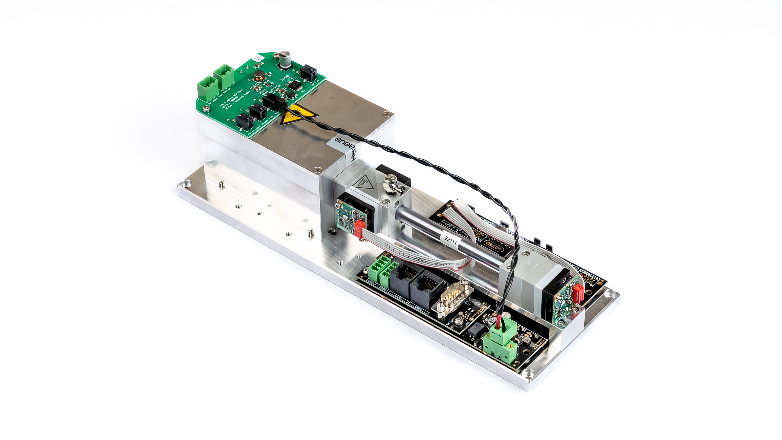
Описание
Приложения
Технические характеристики
Общие характеристики
Измерительная техника: Инновационный датчик NDUV
(недисперсионный ультрафиолетовый датчик)
Двойной лучОбнаруживаемые газы: Количество одновременно обнаруживаемых газов: max. 2 Диапазоны измерений: См. Таблица диапазонов измерений Диапазон расхода воздуха: 5 ~ 300 ltr/h
При больших расходах датчик может работать в режиме байпасаМакс. давление газа на входе: 300 mbar Потеря давления (без дополнительных опциональных датчиков): 10 @ 100 / 35 @ 200 / 70 @ 300 (mbar @ ltr/h) Температурная компенсация: Да Программное обеспечение для сбора данных: Да Срок службы источника ультрафиолетового излучения: > 8 000 h Мерная чаша: Нержавеющая сталь с силиконовым покрытием внутри Герметизация кюветы: Витоновое уплотнительное кольцо Внутренние трубки: FKM / Viton (фторированный каучук) кожух: Высококачественный корпус столешницы, алюминий Размеры (Ширина x Высота x Длина): 300 x 100 x 81 mm Вес: примерно 1670 g Газовые соединения: ПВДФ резьбовое соединение для трубок Øвнутри 4 мм, Øза пределами 6 мм Данные измерений
Ошибка линейности: < ± 1% F.S. Повторяемость: ± 0,5% F.S. Долгосрочная стабильность нулевая: < ± 1% F.S. / 24 h Долгосрочный диапазон стабильности: < ± 1% F.S. / месяц Влияние температуры на нулевую точку: < 1% F.S. / 10K Влияние температуры на пролет: < 2% F.S. / 10K Перекрестная чувствительность: < 2% F.S. Влияние давления: < 1.5% / 10 hPa of reading Время разминки: 1 min (первоначальный), < 15 min для получения полной спецификации Время отклика (t90): 1.5 – 15 sec Частота дискретизации с помощью программного обеспечения: ≤ 10 Hz Предел обнаружения: См. Таблица диапазонов измерений Разрешение: 0,5 x предел обнаружения Электрические характеристики
Электропитание: 24 VDC вкл. вилку питания 100 ~ 240 VAC
50/60 Hz: 24 VDC Ток питания (пик): < 0.4 A Средняя потребляемая мощность: < 7,5 W Интерфейс: USB (стандарт)
RS232 / CANbus / CANopen (опции)
вкл. кабель передачи данных 1 м Аналоговый выход напряжения (Опция): 0-2 V / 0-5 V / 0-10 V Параметры газа
Рабочая температура: +5 ~ +45 °C Температура хранения: –20 ~ +60 °C Рабочее давление: 800 ~ 1200 hPa (mbar) Влажность окружающей среды: 0 ~ 95% относительная влажность
Необходимо предотвратить образование конденсата внутри датчика!Список стандартных диапазонов измерений *1 ( и пределы обнаружения *2 )
Стандартные диапазоны измерений с соответствующими пределами обнаружения ( % от F.S. *3 ) 100
Vol.%50
Vol.%30
Vol.%20
Vol.%10
Vol.%5
Vol.%1
Vol.%5.000
ppm2.000
ppm1.000
ppm500
ppm300
ppm100
ppm50
ppm10
ppm1
ppm SO2
(< 0,1%)
(< 0,1%)
(< 0,1%)
(< 0,1%)
(< 0,1%)
(< 0,1%)
(< 0,1%)
(< 0,1%)
(< 0,5%)
(< 0,5%)
(< 0,5%) H2S
(< 0,1%)
(< 0,1%)
(< 0,1%)
(< 0,1%)
(< 0,2%)
(< 0,5%) Перекалибровки
Опции (установлен внутри корпуса датчика)
Датчик кислорода
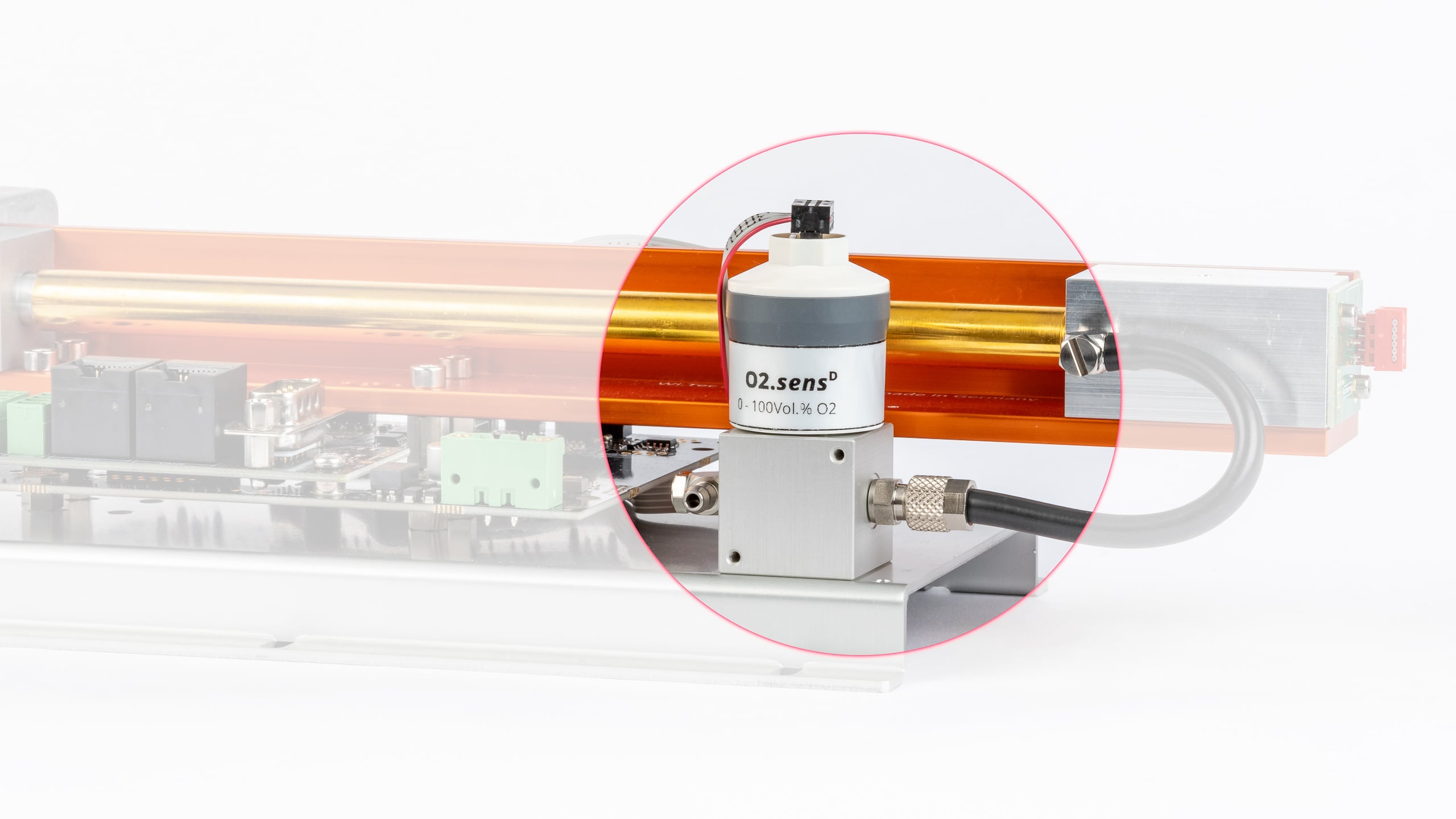
Обзор
Технические характеристики
Общие характеристики
Версия Стандартная версия H2S устойчивое исполнение Диапазон измерений 0 – 25 Vol.% O2 0 – 100 Vol.% O2 0,5 – 35 Vol.% O2 Применение Биогаз, автомобильный анализатор выхлопных газов Промышленный, полностью устойчивый к CO2 Промышленный, полностью устойчивый к CO2,
демонстрирует высокую устойчивость к воздействию кислотных газовСредние контактные материалы ABS, FKM, PPS, PTFE, нержавеющая сталь ABS, PVC, PPS, PTFE, нержавеющая сталь ABS, PVC, PPS, PTFE,
нержавеющая стальОжидаемый срок эксплуатации 1.000.000 Vol.% O2 h ~ 1.200.000 Vol.% O2 h ~ 1.200.000 Vol.% O2 h Срок службы датчика 4 года при температуре окружающего воздуха,
в зависимости от применения6 лет при температуре окружающего воздуха,
в зависимости от применения6 лет при температуре окружающего воздуха Размеры
(Высота x Ширина x Длина)65,4 mm × 31,7 mm × 56,6 mm Вес 70 g Соединитель трубки 4/6 mm труба Данные измерений *
Версия Стандартная версия H2S устойчивое исполнение Диапазон измерений 0 – 25 Vol.% O2 0 – 100 Vol.% O2 0,5 – 35 Vol.% O2 Разрешение 0,1 Vol.% 0,1 Vol.% 0,1 Vol.% Время отклика (t90) < 3,5 s < 10 s < 5 s Дрифт ** < 1% в месяц < 1% в месяц < 3% в месяц Ошибка линейности 0 – 2 Vol.% O2: ± 0,1 абс.
2,1 – 100 Vol.% O2: ± 0,05 относительный0 – 2 Vol.% O2: ± 0,1 абс.
2,1 – 35 Vol.% O2: ± 0,05 относительныйПовторяемость *** ± 1 Vol.% O2 ± 1 Vol.% O2 Влияние влажности –0,03 % относительный O2-измеренное значение /
% RH–0,03 % относительный O2-измеренное значение /
% RH–0,03 % относительный O2-измеренное значение /
% RHПомехи CO2: до 20 Vol.%
CO: до 2000 ppm
NOx: до 5000 ppm
HC: до 5000 ppm
N2O: до 500 ppm< 20 ppm O2 ответ на:
100 Vol.% CO
100 Vol.% CO2
100 Vol.% C3H8
3000 ppm NO на N2
1000 ppm C6H6 на N2
500 ppm SO2 на N2
< 100 ppm O2 ответ на:
3000 ppm C2H6O
3000 ppm C4H10S
< 200 ppm O2 ответ на:
3000 ppm C2H6S2
< 400 ppm O2 ответ на:
100 Vol.% H2
< 500 ppm O2 ответ на:
2000 ppm H2S на N2< 20 ppm O2 ответ на:
100 Vol.% CO
100 Vol.% CO2
100 Vol.% C3H8
1000 ppm C6H6 на N2
2000 ppm H2S на N2
< 20000 ppm O2 ответ на:
3000 ppm NO на N2
1000 ppm H2 на N2
500 ppm SO2 на N2
** в среднем за 12 месяцев
*** @ 100 Vol.% O2 наносится на 5 минПараметры газа
Версия Стандартная версия H2S устойчивое исполнение Диапазон измерений 0 – 25 Vol.% O2 0 – 100 Vol.% O2 0,5 – 35 Vol.% O2 Рабочая температура 0 – 40 °C
прерывистый 40 – 50 °C0 – 45 °C 0 – 50 °C Температура хранения -20 – 40 °C
5 – 25 °C рекомендуется
40 – 50 °C макс. 1 неделя5 – 30 °C рекомендуется
-20 – 50 °C максимальныйДавление воздуха 650 – 1250 hPa (mbar) 700 – 1250 hPa (mbar) 600 – 1250 hPa (mbar) Влажность окружающей среды 0 – 95% относительная влажность (не конденсируется) Датчик давления
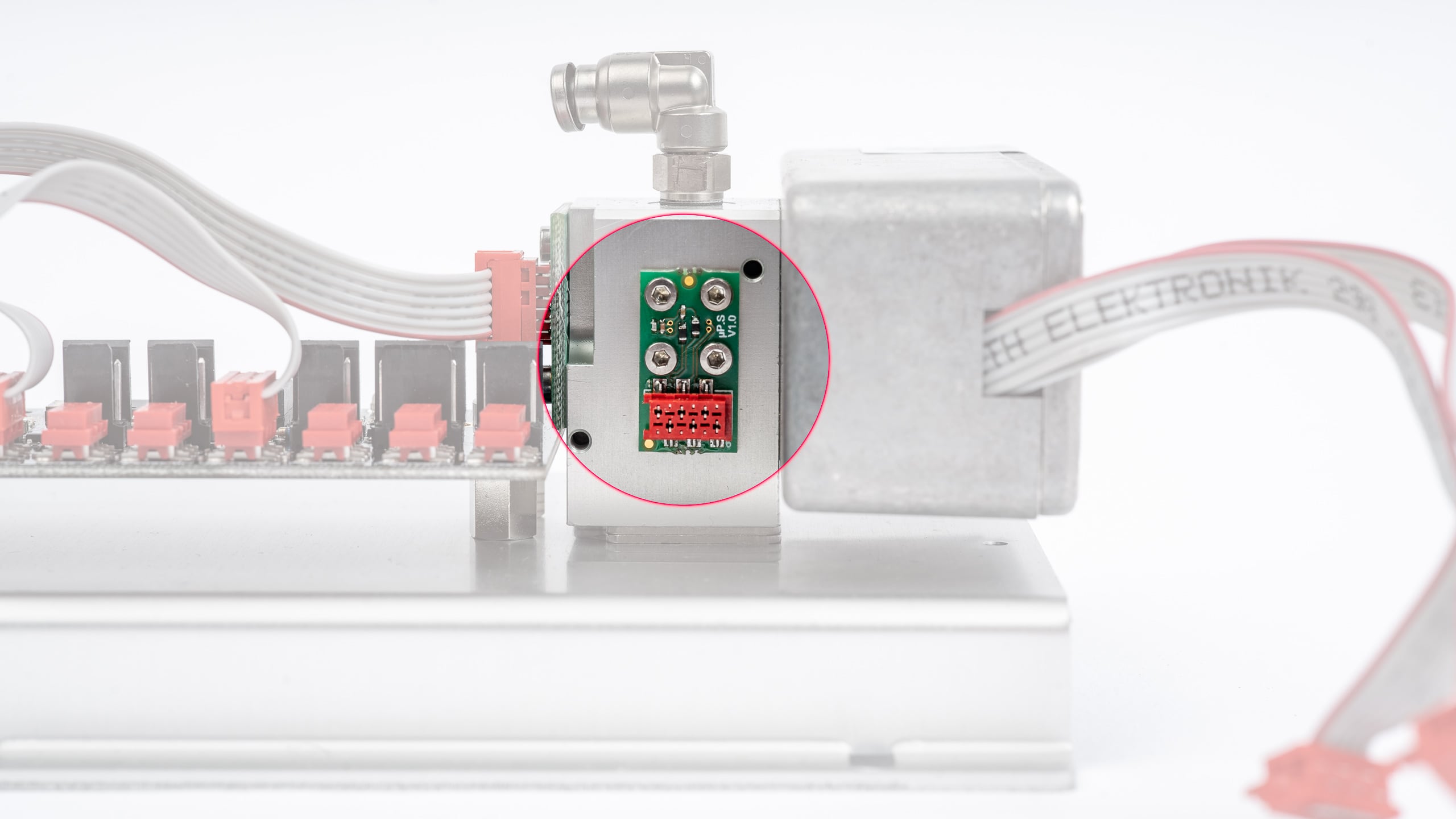
Обзор
Технические характеристики
Датчик влажности
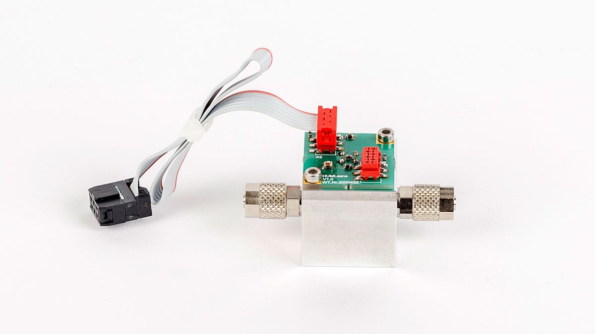
Обзор
Технические характеристики
RITTER »MultiGas« Модуль регулировки нулевой точки (Воздух)
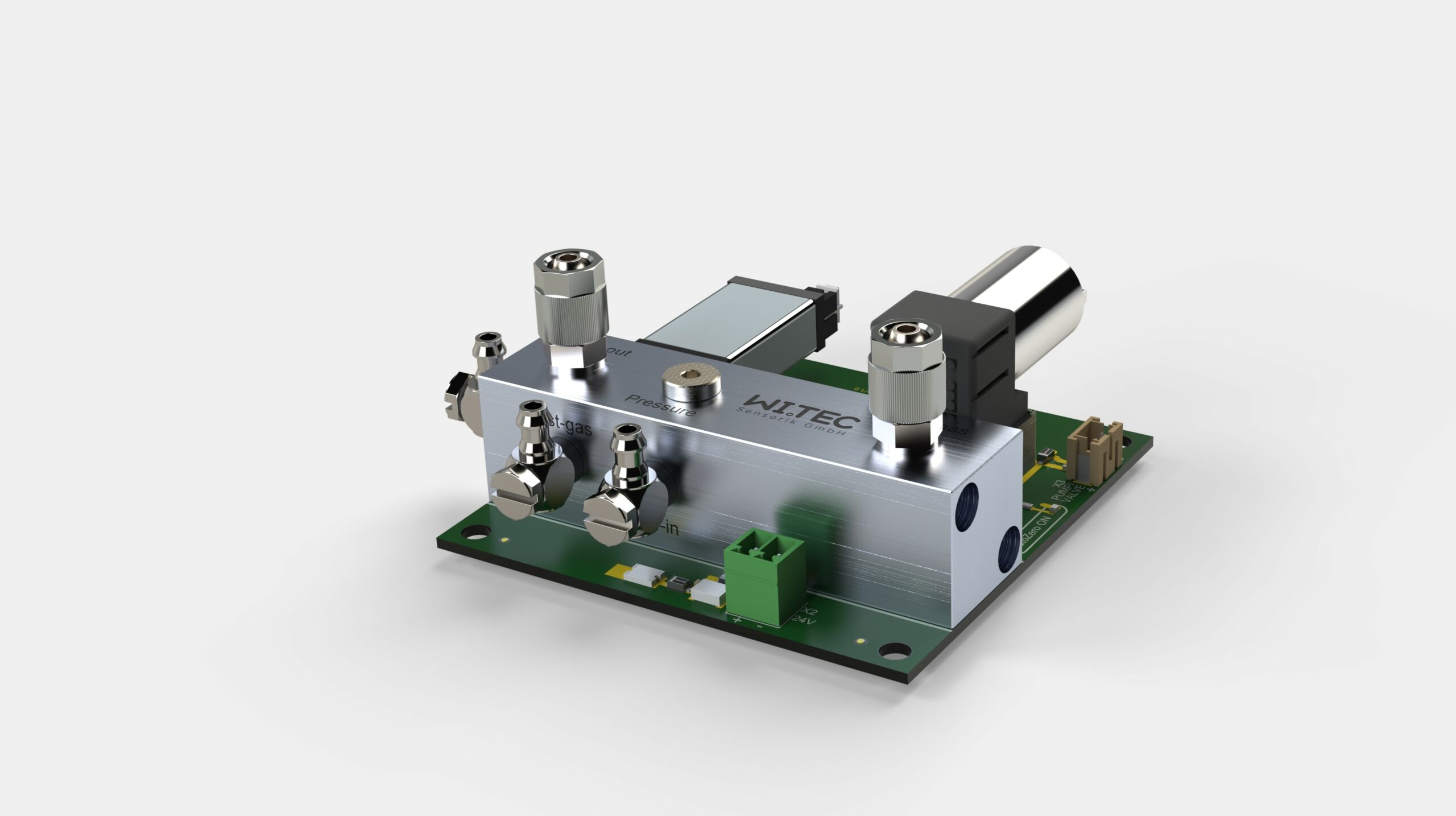
Обзор
Характеристики
Технические характеристики
Перепад давления
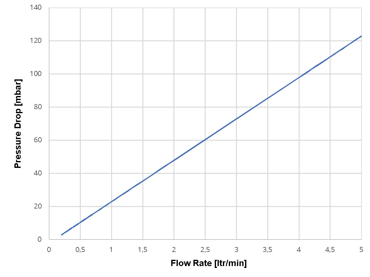
Принципиальная схема
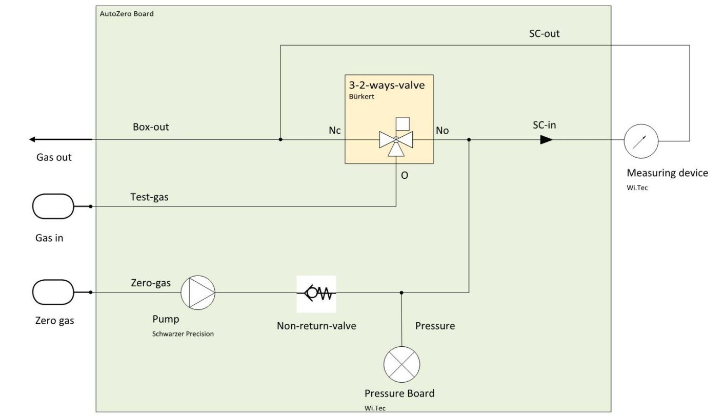
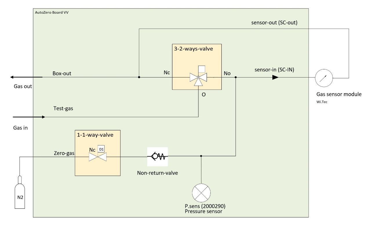
RITTER »MultiGas« Модуль регулировки нулевой точки (N2)
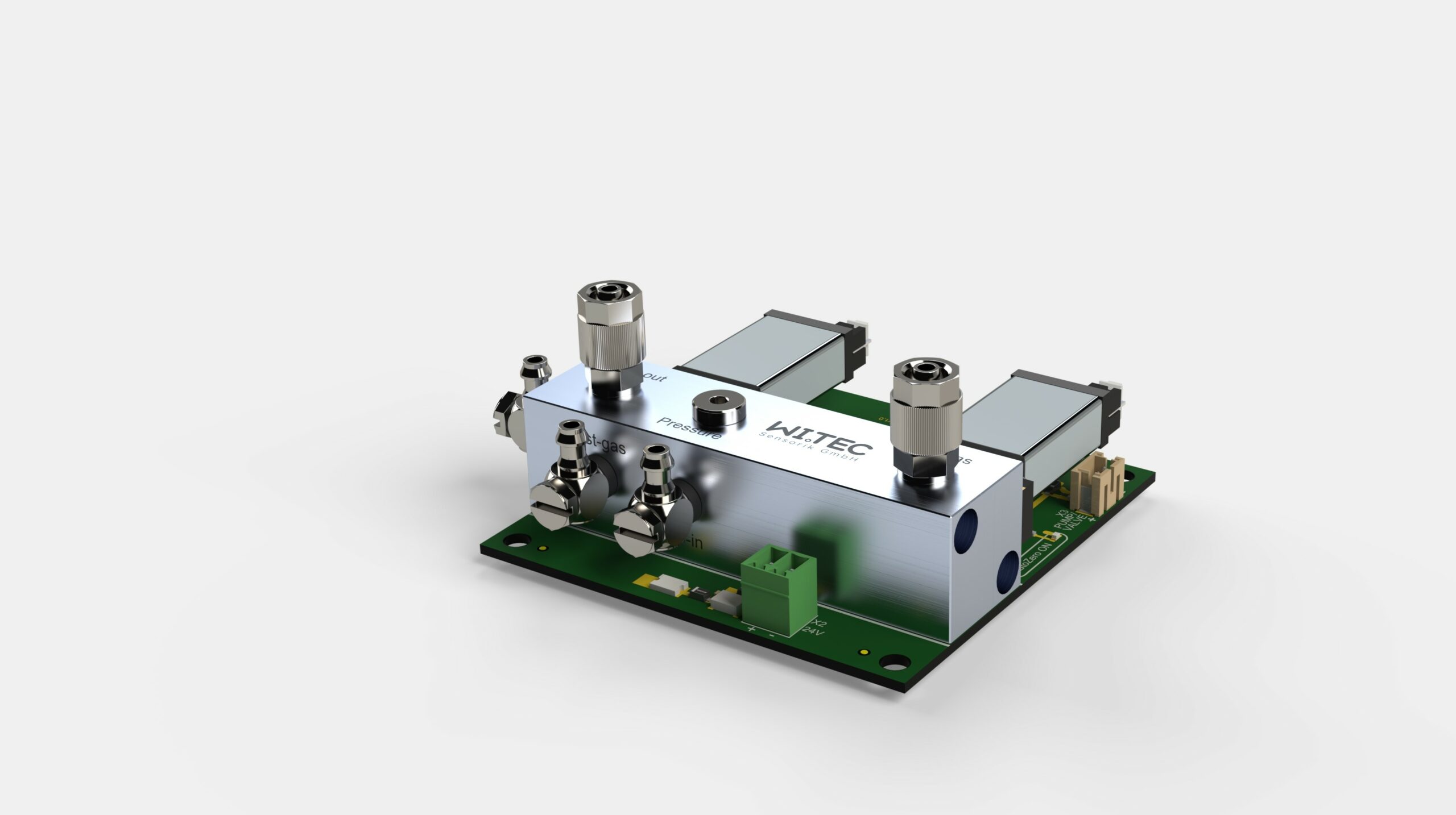
Обзор
Характеристики
Технические характеристики
Перепад давления

Принципиальная схема
Аналоговый выход напряжения
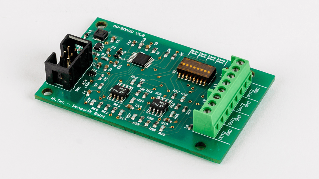
Обзор
Технические данные


Контактный номер. Назначение на канал Цвета проводов предусмотренного соединительного кабеля 1 канал 1 белый 2 канал 2 зеленый 3 канал 3 желтый 4 канал 4 серый 5 ground коричневый Нагрев и термостатирование корпуса датчика
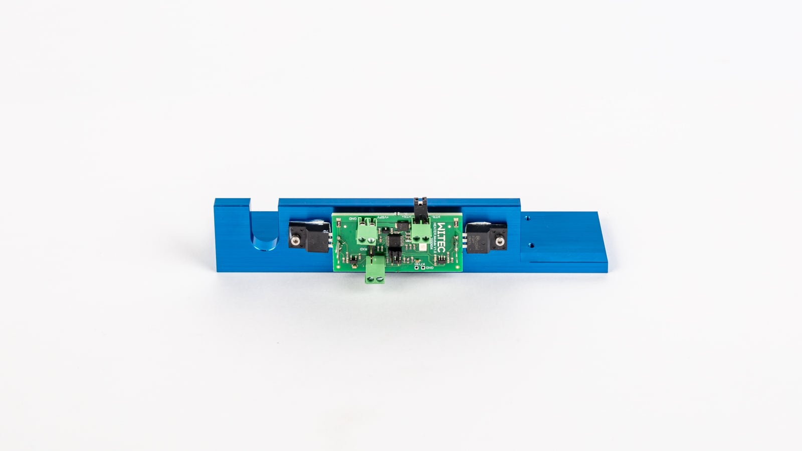
Обзор
Характеристики
Фильтр
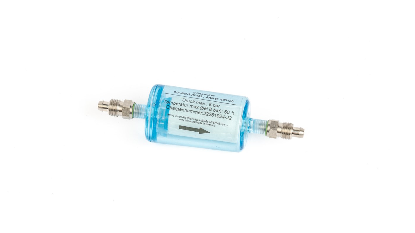
Обзор
Описание
Приложения
Характеристики
Размеры
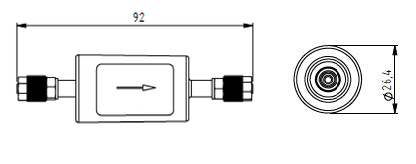
Технические характеристики
Общие характеристики
Размеры Ø 26,4 mm x 92 mm Вес 26 g Соединитель трубки 4/6 mm труба Расход 0 – 4 ltr/min Применение Фильтр частиц Объем жилья 110 ml Средние контактные материалы Полиамид (корпус), нержавеющая сталь (соединитель), FKM (уплотнительное кольцо) Интервал обмена Зависит от загрязненности газа Перепад давления (mbar) @ 1 ltr/min < 6 mbar Параметры газа
Рабочая температура -5 °C – 60 °C Температура хранения -20 °C – 110 °C Макс. давление 8 bar Влажность окружающей среды 0 – 95% относительная влажность (без конденсации) 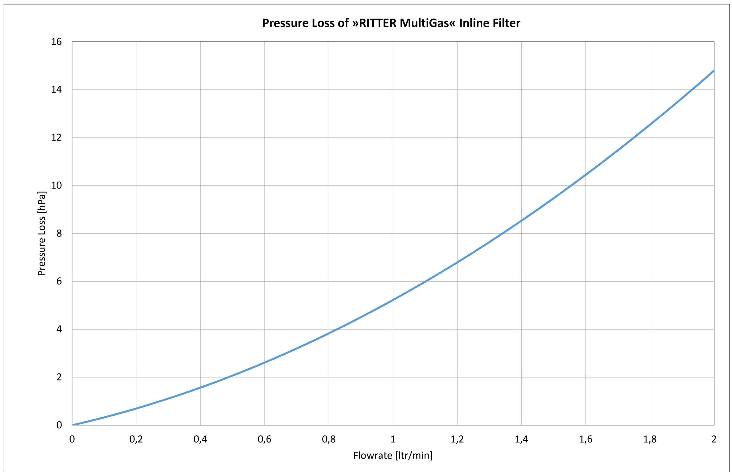
Насос для отбора проб газа

Обзор
Приложения
Характеристики
Размеры

Технические характеристики
Общие характеристики
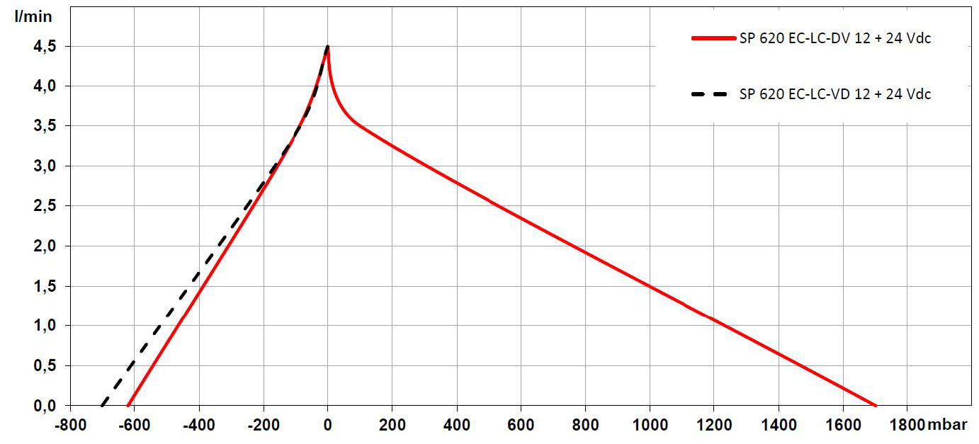
Рабочее напряжение 24 VDC Макс. номинальный ток 330 mA Пневматический разъем 4/6 mm труба Скорость потока 0 – 4,5 ltr/min Макс. давление 1,7 bar Максимальный вакуум -620 mbar Средние контактные материалы PVDF (головка насоса)
PTFE (мембраны)
FFKM (клапан и уплотнение)Вес 184 g Размеры Ширина x Высота x Длина 31 mm x 54 mm x 81,5 mm Параметры газа
Рабочая температура 5 °C – 50 °C Температура хранения -20 °C – 60 °C Влажность окружающей среды 0 – 95% относительная влажность (не конденсируется) Диаграмма производительности
