- 1 Allgemeine Spezifikationen
- 2 Nachteile von elektrochemischen (EC) Sensoren gegenüber den optischen RITTER »MultiGas« Sensoren
- 3 Vorbeugende / schützende Maßnahmen bei Gasmessungen
- 4 Lieferumfang
- 5 Installation
- 6 Infrarot-Sensoren
- 7 Ultraviolett-Sensoren
- 8 Optionen (im Inneren des Sensorgehäuses installiert)
Allgemeine Spezifikationen
Gehäuse-Typen


Abmessungen & Spezifikationen
Gehäuse-Typ 1 Gehäuse-Typ 2 A 171 mm 444 mm B 290 mm (1) 305 mm C 86 mm 145 mm Gewicht, ca. (2) 2+ kg 6,5 – 8 kg Anschluss Gas-Ein-/Ausgang PVDF-Schlauchverschraubungen für Schlauch Øi 4 mm, Øa 6 mm Anschluss-Schlauch PVC Rauclair Øi 4 mm, Øa 6 mm, 3 m Schnittstellen USB (Standard), RS232 / CANbus / CANopen (optional), MODbus auf Anfrage Stromversorgung 24 VDC, inkl. Steckernetzteil
100 – 240 VAC, 50/60 Hz
(2) Je nach Typ und Anzahl der eingebauten Sensormodule.
Schnittstellen
USB
- Typ: USB 2.0
- Buchse: Typ B
- Verbindungskabel: Typ B /
Typ A
RS232
- Typ: RS232
- Buchse: D-sub9 Buchse
- Verbindungskabel: D-sub9 1:1 Stecker/Stecker
CANopen
- Protokoll-Typ: CANopen Modus 2
- Übertragungsrate: 250 kBaud
- Node ID: 0x31
- Buchse: RJ45
CANbus
- Protokoll-Typ: CANbus Modus 1
- Übertragungsrate: 250 kBaud
- Sende-ID: 0x208
- Empfangs-ID: 0x300
- Buchse: RJ45
MODbus
- Übertragungsrate: 250 kBaud
- Databits: 8
- Stopbit: 1
- Parity: None
- Float Definition: IEE754
- Verfügbare Register:
- Read Holding Register 0x03
- Read Input Register 0x04
- Write Single Register 0x06
- Buchse: RJ45
Sensortypen und mögliche Sensorkombinationen
Teil 1: Vorkonfigurierte Sensoren inkl. Gehäuse Typ 1
Mit Gasanschluss‐Verschraubungen, Datenschnittstelle, Steckernetzteil – Gebrauchsfertig
Sensor-Typ:
RITTER MultiGas xxxArtikel
Nr.Gruppe von Gasen
IRAnzahl analysierbarer Gase
in GruppeGruppe von Gasen
UVAnzahl analysierbarer Gase
in Gruppe xxx = mono IR1 2678 1 xxx = duo IR2 2742 2 xxx = trio IR3 2743 3 xxx = mono UV1 2749 1 xxx = mono UV1
Cl2 30%2763 1 xxx = duo UV2 2766 2 xxx = duo IR1 + UV1 2797 1 1 xxx = trio IR1 + UV2 na 1 2
Teil 2: Vorkonfigurierte Sensoren inkl. Gehäuse Typ 2
Mit Gasanschluss‐Verschraubungen, Datenschnittstelle, Steckernetzteil – Gebrauchsfertig
Sensor-Typ:
RITTER MultiGas xxxArtikel
Nr.Gruppe von Gasen
IRAnzahl analysierbarer Gase
in GruppeGruppe von Gasen
UVAnzahl analysierbarer Gase
in Gruppe xxx = mono UV1
H2S ≤ 5000 ppm2672 1 xxx = mono UV1
H2S ≤ 1%2855 1 xxx = UVRAS 2812 1 xxx = duo IR1
+ H2S ≤ 5000 ppm2959 1 1 xxx = duo IR1
+ (H2S ≤ 1% / NO)2960 1 1
Teil 3: Einzelne Sensor‐Module
Zusammenstellung nach Kundenspezifikation, Lieferung inkl. Gehäuse in passender Größe nach Anzahl und Art der Module - Gebrauchsfertig
Sensor-Typ:
RITTER MultiGas xxxArtikel
Nr.Gruppe von Gasen
IRAnzahl analysierbarer Gase
in GruppeGruppe von Gasen
UVAnzahl analysierbarer Gase
in Gruppe xxx = Mod IR1 2813 1 xxx = Mod IR2 2814 2 xxx = Mod IR3 2815 3 xxx = Mod UV1 2830 1 xxx = Mod UV1
Cl2 30%na 1 xxx = Mod UV1
H2S ≤ 5000 ppm2841 1 xxx = Mod UV1
H2S ≤ 1%2856 1 xxx = Mod UV2 2831 2 xxx = Mod UVRAS 2917 3
Teil 4: Gehäuse für Sensor‐Module
Zusammengestellt nach Kundenspezifikation
Gehäuse-Typ:
RITTER MultiGasArtikel
Nr.Gehäuse-Typ Geeignet für xxx = Cas-2 (1) 2817 Gehäuse-Typ 2 Mehrere Module 444 x 305 x 145 mm xxx = Cas-3 (1) 2818 Gehäuse-Typ 3 Mehrere Module 444 x 305 x 189 mm
Teil 5: Eingebaute Optionen
Options-Typ:
RITTER MultiGasArtikel
No.Beschreibung Messbereich RMS-O2 (2) (3) 2795 Sauerstoff‐Sensor 0 ‐ 25% RMS-O2 (2) (3) 2767 Sauerstoff‐Sensor 0 – 100% RMS-O2-resist (3) 2824 Sauerstoff‐Sensor
H2S resistent0,5 – 35% RMS-P (2) (3) 2771 Druck‐Sensor 800 – 1200 mbar abs.
Auflösung <1 mbar RMS-P-resist (3) 2825 Druck‐Sensor
H2S resistent0,2 – 3,5 bar abs.
Auflösung 2 mbar RMS-H (2) (3) 2773 Feuchte‐Sensor 0 – 100% RH RMS-A/O 2648 Analoger Spannungsausgang
0-2 V / 0-5 V / 0-10 V4 analoge Ausgänge für 4 verschiedene Gaskonzentrationen
16 bit RMS‐CasHeat 2954 Thermostatisiertes Gehäuse Heizung und Thermostatisierung des Sensorgehäuses bei 45 °C
(3) Nur als Ergänzung zum IR‐ oder UV‐Sensor verfügbar
Teil 6: Zubehör / Optionen
Options-Typ:
RITTER MultiGas xxxArtikel
No.Beschreibung Messbereich xxx = Cal-ZP-N2 2805 Kalibriergas N2 Für Nullpunkt‐Kalibrierung aller Gase xxx = Flow-V 2806 Mini‐Durchflussventil Regelung der Durchflussmenge für Kalibriergasflasche
Inkl. Manometer xxx = Cal-CG-Cat1 2948 Kalibrierung mit speziellem Trägergas (Ar, H2, He)
für Gase der Kategorie 1Gase der Kategorie 1:
xxx = Cal-CG-Cat2 2949 Kalibrierung mit speziellem Trägergas (Ar, H2, He)
für Gase der Kategorie 2Gase der Kategorie 2:
xxx = Cal-ReCal-Cat1 2950 Rekalibrierung für Gase der Kategorie 1 Gase der Kategorie 1:
xxx = Cal-ReCal-Cat2 2951 Rekalibrierung für Gase der Kategorie 2 Gase der Kategorie 2:
Infrarot-Modul NDIR Ultraviolett-Modul NDUV
Kalibrierungen
In Abhängigkeit der Anzahl zu analysierenden Gase muss ein geeignetes Kalibriergas gewählt werden. Weiterhin beeinflusst die Gasart ebenfalls das optimale Kalibriergas. Wegen der nahezu unendlichen Anzahl der möglichen Kombinationen soll die folgende Aufstellung daher nur als ein erster Überblick verstanden werden.
Messung feuchter Gase
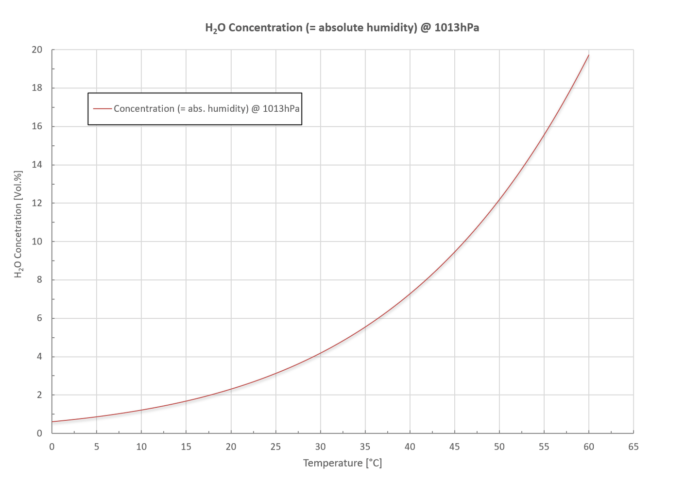
Bei der Messung feuchter Gase muss unbedingt verhindert werden, dass eine Kondensation des Wasserdampfes im Inneren des Sensors erfolgt. Das folgende Diagramm zeigt die maximale Wasserdampf-Konzentration ( = absolute Feuchte) in Volumen-% in Abhängigkeit der Temperatur beim Standarddruck 1013 mbar.
Aus dem Diagramm ist ersichtlich:
Kondensation kann durch folgende Maßnahmen verhindert werden:
Mit dem optionalen Feuchtesensor kann die relative Feuchte im Messbereich: 0 ~ 100% rH sowie die absolute Feuchte in g/m³ gemessen und in der mitgelieferten Software angezeigt werden. Furthermore, the absolute humidity can be measured as well in g/m³. Both values are displayed in the supplied software.
Nachteile von elektrochemischen (EC) Sensoren gegenüber den optischen RITTER »MultiGas« Sensoren
Vorbeugende / schützende Maßnahmen bei Gasmessungen
Wichtig: Bitte geben Sie bei Bestellung die gewünschten Optionen an
a) Zusätzlicher Schlauchanschluss zur Spülung des Gehäuses
Die Gasleitungen im Inneren des Gehäuses und der Messküvette sind durch O-Ringe und andere gasdichte Anschlüsse verschlossen. Wie bei allen Verbindungen ist jedoch eine geringe Leckrate nicht auszuschließen. Mit einem zusätzlichen Schlauchanschluss zur Spülung des Gehäuses können Rückstände des Messgases im Inneren des Gehäuses vermieden werden.
Bei giftigen oder aggressiven Gasen kann über diesen Anschluss eine Saugleitung verbunden werden, die im Gehäuse einen Unterdruck erzeugt und so das Entweichen des Gases aus dem Gehäuse verhindert.
Bei entzündlichen Gasen (Methan, Wasserstoff etc.) kann eine Druck- oder Saugleitung angeschlossen werden, die einen Über- oder Unterdruck im Gehäuse erzeugt und damit die Ansammlung eines entzündlichen Gasgemisches verhindert.
Bitte beachten Sie: H2S kann bereits im ppb-Bereich als unangenehmer Geruch wahrgenommen werden. Auch bei O-Ring-Abdichtungen können Mikroleckagen auftreten, die durch Spülen des Gehäuses abgeführt werden können.
b) Beheizung / Thermostatisierung des Gehäuses
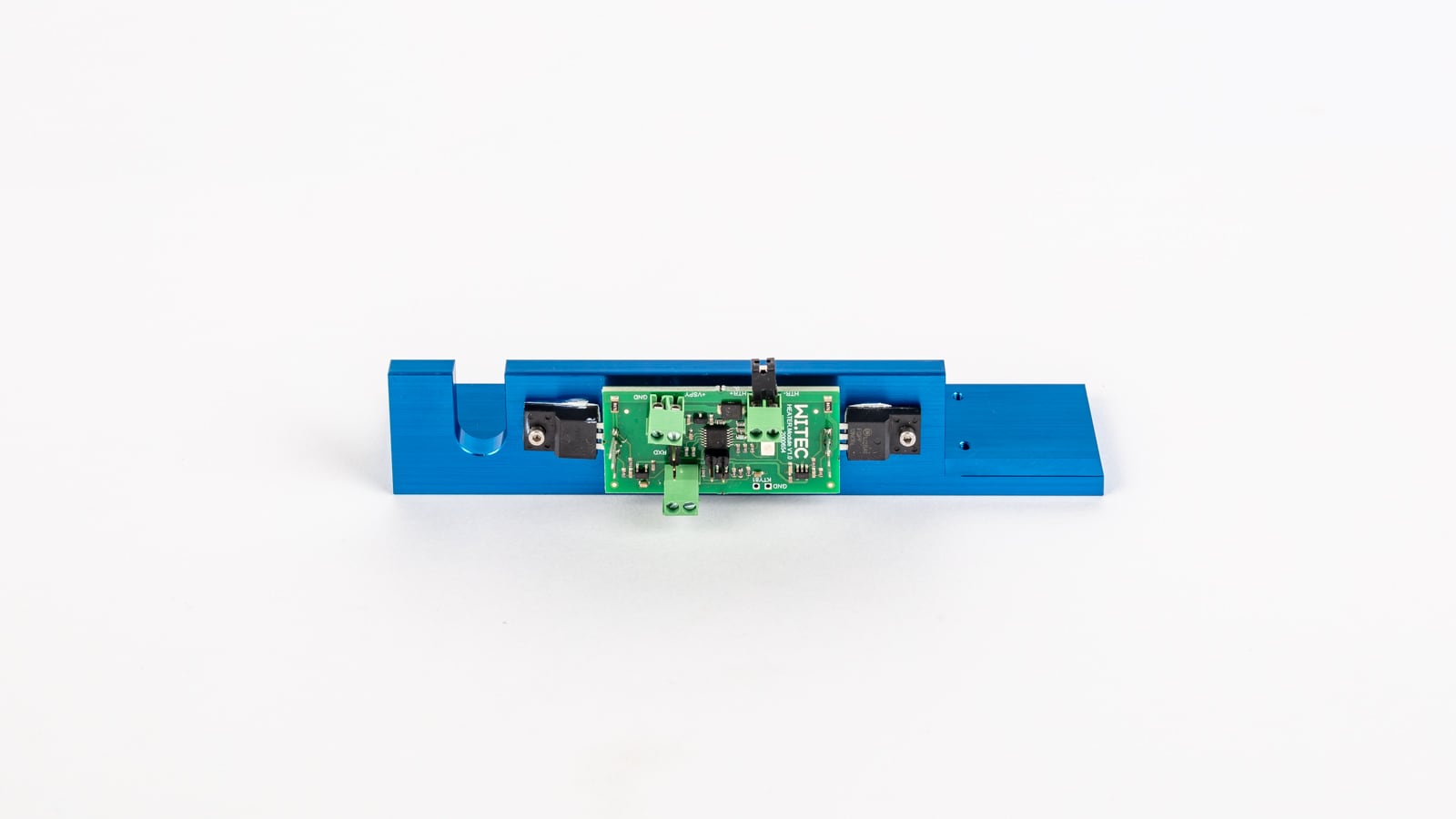
Eine Kondensation des Messgases im Inneren des Sensors muss unbedingt verhindert werden. Dies kann im Allgemeinen mit einer Kondensatfalle oder einem Gaskühler geschehen. Bitte beachten Sie hierzu auch »Messung feuchter Gase«. Alternativ kann das Innere des Sensorgehäuses durch ein Heizelement beheizt und bei 45 °C (standardmäßig) thermostatisiert werden. Dies beugt nicht nur Kondensation im Inneren des Sensors vor, sondern sorgt auch für konstante Messergebnisse. Siehe »Heizung und Thermostatisierung des Sensorgehäuses«.
c) Partikel-Filter
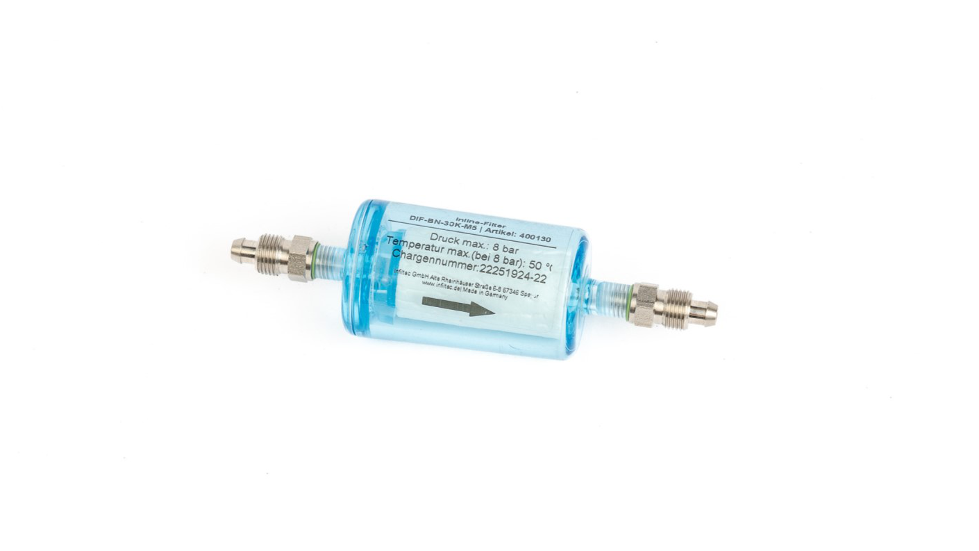
Bitte stellen Sie durch Verwendung eines geeigneten Filters sicher, dass keine Partikel in den Sensor gelangen können. Diese könnten die feinen Durchlässe der internen Anschlüsse verstopfen. Es wird empfohlen, Filter ≤ 5 Mikron zu verwenden.
Lieferumfang
| Anzahl der Artikel | Artikel |
|---|---|
| 1 | Dokumentenmappe inklusive: Kalibrierzertifikat / Datenblätter / Software-Bedienungsanleitung |
| 1 | Sensor in hochwertigem Tischgehäuse |
| 1 | Steckernetzteil Eingang: 100 – 240 V-AC, 50/60 Hz, 0,4 A Ausgang: 24 V-DC, 0,5 A, 12 W oder 36 W (H2S / UVRAS-Sensor) |
| 1 | Software zur Datenerfassung (auf USB-Speicherkarte) |
| 1 | Anschlusskabel: Sensor → PC Standard: USB V2.0 A/B, 1 m Option: RS232, 3m |
| 3m | Viton-Schlauch Øi 4mm / Øa 6mm |
Installation
- Entpacken Sie alle Artikel sorgfältig.
- Installieren Sie die Datenerfassungssoftware gemäß der Bedienungsanleitung »RITTER MultiGas Software«.
Starten Sie die Software zu diesem Zeitpunkt noch nicht. - Positionierung des Sensors:
- Wird der Sensor in Kombination mit einem RITTER-MilliGascounter verwendet, muss der Sensor in Strömungsrichtung vor dem MilliGascounter positioniert werden, wenn dieser mit HCl-Lösung gefüllt ist. Andernfalls könnte der Sensor durch den HCl-Dampf beschädigt werden, der aus dem MilliGascounter austritt.
- Positionieren Sie den Sensor neben der Gasquelle.
Bitte beachten Sie: Eine möglichst kurze Schlauchverbindung zwischen Gasquelle und Sensoren bewirkt einen kleinen Totraum, der durch die Schlauchverbindung entsteht. Ein kleiner Totraum ermöglicht wiederum eine schnelle Ansprechzeit des Sensors.
- Schließen Sie das Netzteil an die Buchse »DC 24 V« auf der Rückseite des Sensors und an das Stromnetz an.
- Schließen Sie das Datenerfassungskabel an den entsprechenden Anschluss auf der Rückseite des Sensors und den Computer an:
- USB-Kabel an die Buchse »USB«
- RS232-Kabel an die Buchse »RS 232« (Option)
- Schließen Sie die Gasquelle an den Gaseingang des Sensors an, indem Sie den mitgelieferten Schlauch wie folgt verbinden:
- Entfernen Sie die Schraubkappen sowie die roten Gummikappen der Transportsicherung vom Gaseingang und Gasausgang.
- Schieben Sie die Schraubkappe auf das Ende des Gaseingang-Schlauches, wobei das Gewinde der Schraubkappe zum Schlauchende zeigt.
- Schieben Sie den Schlauch auf den Konus in der Mitte des Gaseingangs.
- Schieben Sie die Schraubkappe auf den Gaseingang und schrauben Sie diese handfest zu.
- Falls gewünscht: Verbinden Sie den Gasausgang des Sensors mit anderen Komponenten wie z.B. Gas-Speicherbeutel, Abluftschläuche usw. Der Anschluss des Schlauches an den Gasausgang erfolgt auf die gleiche Weise wie oben beschrieben.
- Schalten Sie den Netzschalter an der Vorderseite des Sensorgehäuses ein.
- Starten Sie die Software und öffnen Sie den/die COM-Port(s) des/der angeschlossenen Sensormoduls/Sensormodule entsprechend der Bedienungsanleitung der Software.
Der RITTER »MultiGas« Sensor ist jetzt einsatzbereit.
Infrarot-Sensoren
MultiGas Infrarot-Modul NDIR
Beschreibung
Die Gasanalyse auf Basis der NDIR-Technologie ist eine etablierte Methode, um die Konzentration von Gasen in komplexen Gemischen zu bestimmen. Die RITTER »MultiGas« Sensoren verwenden innovative optische Komponenten für optimale Analyse-Ergebnisse: Bis zu 3 optische Filter analysieren das Gas, welches als Gasstrom durch den Sensor fließt. Die optionalen Sauerstoff-, Druck- und Feuchtesensoren messen dabei denselben Gasstrom.
Die einzelnen internen Module sind durch O-Ring-Verbindungen abgedichtet.
Um eine optimale Anpassung an den gewünschten Messbereich zu erreichen, können die Längen der modularen Messzellen (= Küvetten) im Bereich von 5 mm (großer Messbereich im Prozentbereich) bis 250 mm (kleiner Messbereich im ppm-Bereich) verbaut werden.
Bei Küvettenlängen ≥ 20 mm ist die Innenwand mit einer widerstandsfähigen Goldschicht beschichtet, um die Reflexionseigenschaften für den Nachweis niedriger Konzentrationen zu verbessern und zusätzlichen einen Schutz gegenüber leicht korrosiven Gasen zu gewährleisten.
Die mechanischen Innenteile sind aus Aluminium gefertigt, optional ist auch Edelstahl verfügbar.
Für Anwendungen mit hohen Ansprüchen an die Reaktionszeit liefert das Messsystem ein stabiles Ergebnis innerhalb von t90 ≈ 3 Sekunden.
Die gesamte Einheit kann zur einfachen Wartung und Service demontiert werden.
Anwendungen
Spezifikationen
Allgemeine Merkmale
| Messtechnik: | Innovativer NDIR-Sensor (nicht-dispersiver Infrarot-Sensor) |
| Analysierbare Gase: | CO2 CO N2O CnHm CH4 CF4 SF6 H2O |
| Anzahl der gleichzeitig analysierbarer Gase: | max. 3 pro Sensormodul |
| Messbereiche: | Siehe Tabelle der Messbereiche |
| Volumenstrom-Bereich: | 5 ~ 300 ltr/h Für höhere Durchflussraten kann der Sensor im Bypass betrieben werden. |
| Max. Gas-Eingangsdruck: | 300 mbar |
| Druckverlust (ohne optionale Sensoren): | 10 @ 100 / 35 @ 200 / 70 @ 300 (mbar @ ltr/h) |
| Temperaturausgleich: | Ja |
| Software zur Datenerfassung: | Ja |
| Lebensdauer der IR-Strahlungsquelle: | > 40 000 h |
| Messküvette: | Aluminium, bei Messbereichen ≤1% innen vergoldet |
| Küvettendichtung: | Viton O-Ring |
| Gehäuse: | Hochwertiges Tischgehäuse, Aluminium |
| Abmessungen (W x H x L): | 171 x 86 x 290 mm |
| Gewicht: | ca. 2 kg |
| Gasanschlüsse: | PVDF-Schlauchverschraubung für Schlauch Øi 4 mm, Øa 6 mm |
Messdaten
| Linearitätsfehler: | < ± 1% F.S. |
| Wiederholgenauigkeit: | ± 0,5% F.S. |
| Langfrist-Stabilität Nullpunkt: | < ± 2% F.S. / Woche |
| Langfrist-Stabilität Messbereich: | < ± 2% F.S. / Monat |
| Temperatureinfluss auf Nullpunkt: | < 1% F.S. / 10K |
| Temperatureinfluss auf Messbereich: | < 2% F.S. / 10K |
| Querempfindlichkeit: | < 2% F.S. |
| Druckeinfluss: | < 1.5% / 10hPa vom Messwert |
| Aufwärmzeit: | 2 min |
| Ansprechzeit (t90): | ≈ 3 sec |
| Abtastfrequenz durch Software: | ≤ 10 Hz |
| Nachweisgrenze: | Siehe Tabelle der Nachweisgrenzen |
| Auflösung: | 0,5 x Nachweisgrenze |
| Wasserdampf: | Kein Einfluss auf Messungen von CO2 und CH4 |
Elektrische Merkmale
| Stromversorgung: | 24 VDC inkl. Netzstecker 100 ~ 240 VAC 50/60 Hz: 24 VDC |
| Durchschnittliche Leistungsaufnahme: | < 1W |
| Schnittstellen: | USB (Standard), RS232 / CANbus / CANopen (optional) inkl. Datenübertragungskabel 1 m |
| Analoger Spannungsausgang (Option): | 0 – 2 V / 0 – 5 V / 0 – 10 V |
Gas-Parameter
| Betriebstemperatur: | +15 ~ +45 °C |
| Lagertemperatur: | –20 ~ +60 °C |
| Betriebsdruck: | 800 ~ 1200 hPa (mbar) |
| Umgebungsfeuchtigkeit: | 0 ~ 95% rel. Luftfeuchtigkeit Kondensatbildung im Inneren des Sensors muss verhindert werden! |
* Analyse von CnHm: Die Kalibrierung der Sensoren für CnHm wird mit Propan durchgeführt. Aromatische Kohlenwasserstoffe werden ebenfalls gemessen, jedoch mit einer anderen Gewichtung. Dieses bedeutet, dass die Empfindlichkeit des Sensors bei diesen Gasen deutlich geringer ist als bei anderen Kohlenwasserstoffen.
Liste der Standard-Messbereiche *1 ( und Nachweisgrenzen *2 )
| Standard-Messbereiche mit jeweiligen Nachweisgrenzen ( % vom MBEW *3 ) | ||||||||||||||||
|---|---|---|---|---|---|---|---|---|---|---|---|---|---|---|---|---|
| 100 Vol.% | 50 Vol.% | 30 Vol.% | 20 Vol.% | 10 Vol.% | 5 Vol.% | 1 Vol.% | 5.000 ppm | 2.000 ppm | 1.000 ppm | 500 ppm | 300 ppm | 100 ppm | 50 ppm | 10 ppm | 1 ppm | |
| CO2 | (< 0,1%) | (< 0,1%) | (< 0,1%) | (< 0,1%) | (< 0,1%) | (< 0,1%) | (< 0,1%) | (< 0,1%) | (< 0,1%) | (< 0,1%) | (< 0,3%) | (< 0,3%) | ||||
| CO | (< 0,2%) | (< 0,2%) | (< 0,2%) | (< 0,2%) | (< 0,2%) | (< 0,2%) | (< 0,2%) | (< 0,3%) | (< 0,5%) | (< 0,5%) | ||||||
| N2O | (< 0,1%) | (< 0,1%) | (< 0,1%) | (< 0,1%) | (< 0,1%) | (< 0,1%) | (< 0,1%) | (< 0,3%) | ||||||||
| CnHm*4 | (< 0,1%) | (< 0,1%) | (< 0,1%) | (< 0,2%) | (< 0,2%) | (< 0,2%) | (< 0,2%) | (< 0,5%) | (< 0,5%) | |||||||
| CH4 | (< 0,1%) | (< 0,1%) | (< 0,1%) | (< 0,1%) | (< 0,1%) | (< 0,1%) | (< 0,1%) | (< 0,3%) | (< 0,5%) | |||||||
| CF4 | (< 0,2%) | (< 0,2%) | (< 0,2%) | (< 0,02%) | (< 0,05%) | |||||||||||
| SF6 | (< 0,1%) | (< 0,1%) | (< 0,1%) | (< 0,2%) | (< 0,5%) | (< 0,3%) | (< 0,3%) | |||||||||
| H2O | ||||||||||||||||
Infrarot-Modul NDIR Ultraviolett-Modul NDUV
Definition der Nachweisgrenze
Die Nachweisgrenze ist der kleinste Messwert, der mit einer bestimmten Unsicherheit ermittelt werden kann. Diese Unsicherheit beinhaltet die Auflösung, das Rauschen und die Stabilität des Gassensors für ein bestimmtes Gas und einen bestimmten Messbereich. Zur Ermittlung der Nachweisgrenze werden mehrere Einzelmessungen unter identischen Messbedingungen durchgeführt. Mit den erhaltenen Werten der Einzelmessungen wird die Standardabweichung "Sigma" (σ) berechnet. Die in der Tabelle angegebenen Werte entsprechen dem dreifachen Betrag von Sigma.
Rekalibrierung
Für IR-Sensoren werden die folgenden Rekalibrierungs-Intervalle empfohlen:
Ultraviolett-Sensoren
Der RITTER »MultiGas« UV-Sensor ist das weltweit erste Gasanalyse-Modul, welches auf miniaturisierten UV-LEDs basiert. Die Stabilität und Lebensdauer dieser UV-LEDs ermöglicht hochpräzise Gasanalysen bis in den ppm-Bereich. Durch den Einsatz von zwei UV-LEDs können zwei Gase gleichzeitig detektiert werden. Darüber hinaus können mit diesem Ansatz Messbereiche von ppm bis Vol.-% realisiert werden. Im Spektralbereich von 200 nm bis 500 nm können mit dieser neuen Sensorplattform Stickoxide (NO + NO2), aromatische Kohlenwasserstoffe, Schwefelwasserstoff, Ozon, Schwefeldioxid und Chlor zuverlässig nachgewiesen werden. Die gesamte Einheit kann zur einfachen Wartung und Service demontiert werden. Die einzelnen internen Module sind durch O-Ring-Verbindungen abgedichtet. Um eine optimale Anpassung an den gewünschten Messbereich zu erreichen, können die Längen der modularen Messzellen (= Küvetten) im Bereich von 5 mm (großer Messbereich im Prozentbereich) bis 250 mm (kleiner Messbereich im ppm-Bereich) verbaut werden. Bei Küvettenlängen ≥ 20 mm ist die Innenwand mit einer widerstandsfähigen Goldschicht beschichtet, um die Reflexionseigenschaften für den Nachweis niedriger Konzentrationen zu verbessern. Die mechanischen Innenteile sind aus Aluminium gefertigt, optional ist auch Edelstahl verfügbar. Für Anwendungen mit hohen Ansprüchen an die Reaktionszeit liefert das Messsystem ein stabiles Ergebnis innerhalb von t90 ≈ 1-2 Sekunden. Infrarot-Modul NDIR Ultraviolett-Modul NDUV Definition der Nachweisgrenze Die Nachweisgrenze ist der kleinste Messwert, der mit einer bestimmten Unsicherheit ermittelt werden kann. Diese Unsicherheit beinhaltet die Auflösung, das Rauschen und die Stabilität des Gassensors für ein bestimmtes Gas und einen bestimmten Messbereich. Zur Ermittlung der Nachweisgrenze werden mehrere Einzelmessungen unter identischen Messbedingungen durchgeführt. Mit den erhaltenen Werten der Einzelmessungen wird die Standardabweichung "Sigma" (σ) berechnet. Die in der Tabelle angegebenen Werte entsprechen dem dreifachen Betrag von Sigma. Für UV-Sensoren werden folgende Rekalibrierungs-Intervalle empfohlen: Für den Nachweis von NO wird eine EDL (elektrodenlose Gasentladungslampe) verwendet. In der EDL werden N2 und O2 in NO umgewandelt und erzeugen eine selektive UV-Strahlung. Mit dieser Strahlung wird eine querempfindlichskeitsfreie NO-Messung ermöglicht. Diese Methode wird als UV-Resonanz-Absorptions-Spektroskopie (UVRAS) bezeichnet. Eine Kombination der UVRAS- und der NDUV-Technologie ermöglicht die gleichzeitige Gasanalyse von NO, NO2 und SO2 im unteren ppm-Bereich, was besonders bei der Rauchgasanalyse (Continuous Emission Monitoring, CEM) wichtig ist. Infrarot-Modul NDIR Ultraviolett-Modul NDUV Definition der Nachweisgrenze Die Nachweisgrenze ist der kleinste Messwert, der mit einer bestimmten Unsicherheit ermittelt werden kann. Diese Unsicherheit beinhaltet die Auflösung, das Rauschen und die Stabilität des Gassensors für ein bestimmtes Gas und einen bestimmten Messbereich. Zur Ermittlung der Nachweisgrenze werden mehrere Einzelmessungen unter identischen Messbedingungen durchgeführt. Mit den erhaltenen Werten der Einzelmessungen wird die Standardabweichung "Sigma" (σ) berechnet. Die in der Tabelle angegebenen Werte entsprechen dem dreifachen Betrag von Sigma. Für UV-Sensoren werden folgende Rekalibrierungs-Intervalle empfohlen: Der H2S-Sensor arbeitet nach dem Prinzip der nicht-dispersiven UV-Absorption (NDUV). Die verwendete Messwellenlänge liegt im unteren Nanometerbereich, was interferenzfreie Messungen mit Wasserdampf und Kohlenwasserstoffen ermöglicht. Der Sensor ist daher ideal für den Einsatz bei Biogasmessungen, da Begleitgase wie NH3, CO2, CH4 und H2O die Messgenauigkeit nicht beeinträchtigen. Im Gegensatz zu fotometrischen NDUV-Sensoren, ist die Lebensdauer von elektrochemischen Sensoren bei der Messung von H2S begrenzt. Bitte beachten Sie, dass bei diesen Sensoren sich die Angaben zur Lebensdauer auf Messungen mit Luft beziehen und nicht für H2S gültig sind. Bei H2S-Konzentrationen >200 ppm ist die Lebensdauer verringert, bei >1000 ppm deutlich verringert. Während die Messleistung der UV-LED konstant ist, werden EC-Sensoren »taub«. Infrarot-Modul NDIR Ultraviolett-Modul NDUV Definition der Nachweisgrenze Die Nachweisgrenze ist der kleinste Messwert, der mit einer bestimmten Unsicherheit ermittelt werden kann. Diese Unsicherheit beinhaltet die Auflösung, das Rauschen und die Stabilität des Gassensors für ein bestimmtes Gas und einen bestimmten Messbereich. Zur Ermittlung der Nachweisgrenze werden mehrere Einzelmessungen unter identischen Messbedingungen durchgeführt. Mit den erhaltenen Werten der Einzelmessungen wird die Standardabweichung "Sigma" (σ) berechnet. Die in der Tabelle angegebenen Werte entsprechen dem dreifachen Betrag von Sigma. Für UV-Sensoren werden folgende Rekalibrierungs-Intervalle empfohlen: Der Sauerstoffsensor ist nur optional als zusätzliches Sensormodul zu den RITTER »MultiGas« NDIR- oder NDUV-Sensoren erhältlich. Die gemessene Sauerstoffkonzentration wird in der mitgelieferten Software angezeigt. Der Sensor ist in das Gehäuse der RITTER »MultiGas« Sensoren eingebaut. Folgende Ausführungen sind verfügbar: * bei Pa = 1013 hPa, Ta = 25 °C, RH = 50%, Durchfluss = 2,5 l/min Eine Veränderung des Gas- und/oder des Atmosphärendrucks beeinflusst die Anzahl von Molekülen pro Volumen und führt damit zu einer Änderung der Gasdichte. Diese Dichteänderung hat wiederum einen wesentlichen Einfluss auf das Ergebnis der Konzentrationsmessung durch den Sensor. Durch die Messung des Gasdrucks im Inneren der Messzelle (Küvette) wird der Messwert der Konzentrationsmessung kompensiert / korrigiert. Der Drucksensor ermöglicht eine Erhöhung der Genauigkeit der Gasanalysemessung um den Faktor 15: Der Drucksensor ist bei den RITTER »MultiGas« NDIR-Sensoren standardmäßig als Mikro-Sensor eingebaut. Bei den NDUV-Sensoren ist dieser optional erhältlich und im Sensorgehäuse eingebaut. Die gemessenen Druckwerte werden in der mitgelieferten Software angezeigt. Ausführung für nicht-aggressive Gase: Ausführung für H2S und ähnliche saure Gase: Der Feuchtesensor ist nur optional als zusätzliches Sensormodul zu einem RITTER »MultiGas« NDIR- oder NDUV-Sensor erhältlich. Er ist in das Gehäuse der RITTER »MultiGas« Sensoren eingebaut. Die gemessenen Feuchtigkeitswerte (absolut und relativ) werden durch die mitgelieferte Software angezeigt. Das analoge Spannungsausgangs-Modul ermöglicht die gleichzeitige Ausgabe von bis zu 4 verschiedenen Messwerten auf 4 separaten Kanälen: Für den Anschluss an ein analoges Datenerfassungsgerät stellt der analoge Spannungsausgang alternativ folgende Spannungspegel zur Verfügung: Der Spannungsbereich ist nach Kundenwunsch voreingestellt und kann vom Anwender nicht verändert werden. Bitte beachten Sie die Zuordnung der jeweiligen Gaskonzentrations-Messungen zu den jeweiligen Kanälen. Diese ist im Kalibrierprotokoll des Sensormoduls angegeben. Zuordnung der Kontakte von Buchse und Stecker des Analogen Spannungsausgangs zu den Kanälen: Analoge Ausgangssignale der Sauerstoff- und Feuchtesensoren: Es kann alternativ nur eines dieser beiden Signale übertragen werden.. Das Anschluss-Kabel wird mit offenen Enden zum Anschluss an das analoge Datenerfassungsgerät des Anwenders geliefert. Die Litzenfarben des Kabels sind in der obenstehenden Tabelle aufgeführt. Um die Kondensation von feuchtem Gas im Inneren des Sensors zu vermeiden, kann das Sensorgehäuse beheizt und thermostatisiert werden. Standardmäßig ist der Temperaturregler auf 45 °C voreingestellt; niedrigere Temperaturen sind auf Anfrage möglich. Das Heizelement und der Temperaturregler sind an der Halterung der Messküvette angebracht. Der Filter für Gaspartikel wird als Zubehör für Anwendungen angeboten, bei denen keine kundenseitige Filtration des Gases erfolgt. Dieser ist als Inline-Filter konzipiert, der einfach in den Gasschlauch vor allen RITTER »MultiGas« Sensoren eingesetzt werden kann. Bitte beachten Sie: Es dürfen keine Partikel in den Sensor gelangen, da diese die kleinen Öffnungen im Inneren des Sensors blockieren würden. Daher wird mit jedem Sensor ein Filter pro Gasleitung geliefert. Der Filter wird mit einer Schlauchverschraubung in den Zuleitungs-Schlauch eingesetzt. Zusätzliche Filter können bei Ihrem nationalen RITTER Vertriebspartner bestellt werden. MultiGas Ultraviolett-Modul NDUV
Beschreibung
Anwendungen
Spezifikationen
Allgemeine Merkmale
Messtechnik: Innovativer NDUV-Sensor
(nicht-dispersiver Ultraviolett Sensor)Analysierbare Gase: Anzahl der gleichzeitig analysierbarer Gase: max. 2 Messbereiche: Siehe Tabelle der Messbereiche Volumenstrom-Bereich: 5 ~ 300 ltr/h
Für höhere Durchflussraten kann der Sensor im Bypass betrieben werden.Max. Gas-Eingangsdruck: 300 mbar Druckverlust (ohne optionale Sensoren): 10 @ 100 / 35 @ 200 / 70 @ 300 (mbar @ ltr/h) Temperaturausgleich: Ja Software zur Datenerfassung: Ja Lebensdauer der UV-Strahlungsquelle: > 8 000 h Messküvette: Edelstahl mit Silikonbeschichtung innen Küvettendichtung: Viton O-Ring Interne Verschlauchung: FKM / Viton (Fluorkautschuk) Gehäuse: Hochwertiges Tischgehäuse, Aluminium Abmessungen (B x H x L): 464 x 189 x 305 mm Gewicht: ca. 6,5+ kg Gasanschlüsse: PVDF-Schlauchverschraubung für Schlauch Øi 4 mm, Øa 6 mm Messdaten
Linearitätsfehler: < ± 1% MBEW (F.S.) Wiederholgenauigkeit: ± 0,5% MBEW (F.S.) Langfrist-Stabilität Nullpunkt: < ± 1% MBEW (F.S.) / 24 h Langfrist-Stabilität Messbereich: < ± 1% MBEW (F.S.) / month Temperatureinfluss auf Nullpunkt: < 1% MBEW (F.S.) / 10K Temperatureinfluss auf Messbereich: < 2% MBEW (F.S.) / 10K Querempfindlichkeit: < 2% MBEW (F.S.) Druckeinfluss: < 1,5% / 10 hPa vom Messwert Aufwärmzeit: 1 min (Inbetriebnahme), < 60 min für volle Spezifikation Ansprechzeit (t90): 1,5 – 15 sec Abtastfrequenz durch Software: ≤ 10 Hz Nachweisgrenze: Siehe Tabelle der Messbereiche Auflösung: 0,5 x Nachweisgrenze Elektrische Merkmale
Stromversorgung: 24 VDC inkl. Netzstecker 100 ~ 240 VAC
50/60 Hz: 24 VDC Stromaufnahme (Spitze) < 0,4 A Durchschnittliche Leistungsaufnahme < 7,5 W Schnittstellen: USB (Standard)
RS232 / CANbus / CANopen (optional)
inkl. Datenübertragungskabel 1 m Analoger Spannungsausgang (Option): 0-2 V / 0-5 V / 0-10 V Gas-Parameter
Betriebstemperatur: +25 ~ +45 °C Lagertemperatur: –20 ~ +60 °C Betriebsdruck: 800 ~ 1200 hPa (mbar) Umgebungsfeuchtigkeit: 0 ~ 95% rel. Luftfeuchtigkeit
Kondensatbildung im Inneren des Sensors muss verhindert werden!Liste der Standard-Messbereiche *1 ( und Nachweisgrenzen *2 )
Standard-Messbereiche mit jeweiligen Nachweisgrenzen ( % vom MBEW *3 ) 100
Vol.%50
Vol.%30
Vol.%20
Vol.%10
Vol.%5
Vol.%1
Vol.%5.000
ppm2.000
ppm1.000
ppm500
ppm300
ppm100
ppm50
ppm10
ppm1
ppm O3
(< 0,1%)
(< 0,1%)
(< 0,1%)
(< 0,2%)
(< 0,5%)
(< 0,5%)
(< 0,5%) CL2
(< 0,1%)
(< 0,1%)
(< 0,1%)
(< 0,1%)
(< 0,1%)
(< 0,1%)
(< 0,1%)
(< 0,2%)
(< 0,5%) SO2
(< 0,1%)
(< 0,1%)
(< 0,1%)
(< 0,1%)
(< 0,1%)
(< 0,1%)
(< 0,1%)
(< 0,1%)
(< 0,5%)
(< 0,5%)
(< 0,5%) H2S
(< 0,1%)
(< 0,1%)
(< 0,1%)
(< 0,1%)
(< 0,2%)
(< 0,5%) NO2
(< 0,1%)
(< 0,1%)
(< 0,1%)
(< 0,2%)
(< 0,2%)
(< 0,5%)
(< 0,5%)
(< 0,5%) NO
(< 0,1%)
(< 0,1%)
(< 0,1%)
(< 0,2%)
(< 0,2%) Rekalibrierung
MultiGas Ultraviolett-Modul NDUV / UVRAS
Beschreibung
Anwendungen
Spezifikationen
Allgemeine Merkmale
Messtechnik: UV-Resonanz-Absorptions-Spektroskopie (UVRAS) Analysierbare Gase: Anzahl der gleichzeitig analysierbarer Gase: max. 3 pro Sensormodul Messbereiche: Siehe Tabelle der Messbereiche Volumenstrom-Bereich: 5 ~ 300 ltr/h
Für höhere Durchflussraten kann der Sensor im Bypass betrieben werden.Max. Gas-Eingangsdruck: 300 mbar Druckverlust (ohne optionale Sensoren): 10 @ 100 / 35 @ 200 / 70 @ 300 (mbar @ ltr/h) Zusätzliche beheizte und thermostatisierte Einhausung im Sensorgehäuse: Ja Temperaturausgleich: Ja Software zur Datenerfassung: Ja Lebensdauer der UV-Strahlungsquellen: LED > 20 000 h (NO2, SO2)
EDL > 8 000 h (NO)Messküvette: Edelstahl mit Silikonbeschichtung innen Küvettendichtung: Viton O-Ring Interne Verschlauchung: FKM / Viton (Fluorkautschuk) Gehäuse: Hochwertiges Tischgehäuse Typ 2, Aluminium Abmessungen (B x H x L): 464 x 189 x 305 mm Gewicht: ca. 6,5+ kg Gasanschlüsse: PVDF-Schlauchverschraubung für Schlauch Øi 4 mm, Øa 6 mm Messdaten
Linearitätsfehler: < ± 1% MBEW (F.S.) Wiederholgenauigkeit: ± 0,5 % MBEW (F.S.) Langfrist-Stabilität Nullpunkt: < 3 ppm / 24 h Langfrist-Stabilität Messbereich: < ± 1 % MBEW (F.S.) / Monat Temperatureinfluss auf Nullpunkt: < 1 % MBEW (F.S.) / 10 K Temperatureinfluss auf Messbereich: < 2 % MBEW (F.S.) / 10 K Querempfindlichkeit: 500 ppm NO2 < 2 ppm
100 ppm SO2 < 2 ppm
100 ppm N2O < 10 ppm
20 °C D.P. H2O < 10 ppm
Druckeinfluss: < 1,5% / 10 hPa vom Messwert Aufwärmzeit: 1 min (Inbetriebnahme), < 60 min für volle Spezifikation Ansprechzeit (t90): 1,5 ~ 15 sec Abtastfrequenz durch Software: ≤ 10 Hz Nachweisgrenze: Siehe Tabelle der Messbereiche Auflösung: 0,5 x Nachweisgrenze Elektrische Merkmale
Stromversorgung: 24 VDC inkl. Netzstecker 100 ~ 240 VAC
50/60 Hz: 24 VDCStromaufnahme (Spitze): 1,5 A Einschaltstrom: 0,2 ~ 0,7 A Leistungsaufnahme: 36 W Schnittstellen: USB (Standard)
RS232 / CANbus / CANopen (optional)
inkl. Datenübertragungskabel 1 mAnaloger Spannungsausgang (Option): 0-2 V / 0-5 V / 0-10 V Gas-Parameter
Betriebstemperatur: +5 ~ +40 °C Lagertemperatur: –20 ~ +60 °C Betriebsdruck: 800 ~ 1200 hPa (mbar) Umgebungsfeuchtigkeit: 0 ~ 95% rel. Luftfeuchtigkeit
Kondensatbildung im Inneren des Sensors muss verhindert werden!Liste der Standard-Messbereiche *1 ( und Nachweisgrenzen *2 )
Standard-Messbereiche mit jeweiligen Nachweisgrenzen ( % vom MBEW *3 ) 100
Vol.%50
Vol.%30
Vol.%20
Vol.%10
Vol.%5
Vol.%1
Vol.%5.000
ppm2.000
ppm1.000
ppm500
ppm300
ppm100
ppm50
ppm10
ppm1
ppm SO2
(< 0,1%)
(< 0,1%)
(< 0,1%)
(< 0,1%)
(< 0,1%)
(< 0,1%)
(< 0,1%)
(< 0,1%)
(< 0,5%)
(< 0,5%)
(< 0,5%) NO2
(< 0,1%)
(< 0,1%)
(< 0,1%)
(< 0,2%)
(< 0,2%)
(< 0,5%)
(< 0,5%)
(< 0,5%) NO
(< 0,1%)
(< 0,1%)
(< 0,1%)
(< 0,2%)
(< 0,2%) Rekalibrierung
MultiGas Ultraviolett-Modul NDUV / H2S
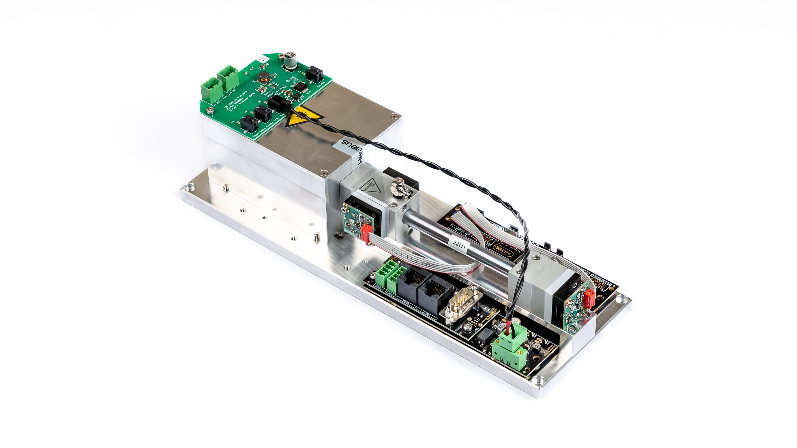
Beschreibung
Anwendungen
Spezifikationen
Allgemeine Merkmale
Messtechnik: Innovativer NDUV-Sensor
(nicht-dispersiver Ultraviolett Sensor)
Dual beamAnalysierbare Gase: Anzahl der gleichzeitig analysierbarer Gase: max. 2 Messbereiche: Siehe Tabelle der Messbereiche Volumenstrom-Bereich: 5 ~ 300 ltr/h
Für höhere Durchflussraten kann der Sensor im Bypass betrieben werden.Max. Gas-Eingangsdruck: 300 mbar Druckverlust (ohne optionale Sensoren): 10 @ 100 / 35 @ 200 / 70 @ 300 (mbar @ ltr/h) Temperaturausgleich: Ja Software zur Datenerfassung: Ja Lebensdauer der UV-Strahlungsquelle: > 8 000 h Messküvette: Edelstahl mit Silikonbeschichtung innen Küvettendichtung: Viton O-Ring Interne Verschlauchung: FKM / Viton (Fluorkautschuk) Gehäuse: Hochwertiges Tischgehäuse, Aluminium Abmessungen (B x H x L): 300 x 100 x 81 mm Gewicht: ca. 1670 g Gasanschlüsse: PVDF-Schlauchverschraubung für Schlauch Øi 4 mm, Øa 6 mm Messdaten
Linearitätsfehler: < ± 1% MBEW (F.S.) Wiederholgenauigkeit: ± 0,5% MBEW (F.S.) Langfrist-Stabilität Nullpunkt: < ± 1% MBEW (F.S.) / 24 h Langfrist-Stabilität Messbereich: < ± 1% MBEW (F.S.) / Monat Temperatureinfluss auf Nullpunkt: < 1% MBEW (F.S.) / 10K Temperatureinfluss auf Messbereich: < 2% MBEW (F.S.) / 10K Querempfindlichkeit: < 2% MBEW (F.S.) Druckeinfluss: < 1,5% / 10 hPa of reading Aufwärmzeit: 1 min (Inbetriebnahme), < 15 min für volle Spezifikation Ansprechzeit (t90): 1,5 – 15 sec Abtastfrequenz durch Software: ≤ 10 Hz Nachweisgrenze: Siehe Tabelle der Messbereiche Auflösung: 0,5 x Nachweisgrenze Elektrische Merkmale
Stromversorgung: 24 VDC inkl. Netzstecker 100 ~ 240 VAC
50/60 Hz: 24 VDC Stromaufnahme (Spitze): < 0,4 A Durchschnittliche Leistungsaufnahme: < 7,5 W Schnittstellen: USB (Standard)
RS232 / CANbus / CANopen (optional)
inkl. Datenübertragungskabel 1 m Analoger Spannungsausgang (Option): 0-2 V / 0-5 V / 0-10 V Gas-Parameter
Betriebstemperatur: +5 ~ +45 °C Lagertemperatur: –20 ~ +60 °C Betriebsdruck: 800 ~ 1200 hPa (mbar) Umgebungsfeuchtigkeit: 0 ~ 95% rel. Luftfeuchtigkeit
Kondensatbildung im Inneren des Sensors muss verhindert werden!Liste der Standard-Messbereiche *1 ( und Nachweisgrenzen *2 )
Standard-Messbereiche mit jeweiligen Nachweisgrenzen ( % vom MBEW *3 ) 100
Vol.%50
Vol.%30
Vol.%20
Vol.%10
Vol.%5
Vol.%1
Vol.%5.000
ppm2.000
ppm1.000
ppm500
ppm300
ppm100
ppm50
ppm10
ppm1
ppm SO2
(< 0,1%)
(< 0,1%)
(< 0,1%)
(< 0,1%)
(< 0,1%)
(< 0,1%)
(< 0,1%)
(< 0,1%)
(< 0,5%)
(< 0,5%)
(< 0,5%) H2S
(< 0,1%)
(< 0,1%)
(< 0,1%)
(< 0,1%)
(< 0,2%)
(< 0,5%) Rekalibrierung
Optionen (im Inneren des Sensorgehäuses installiert)
Sauerstoff‐Sensor
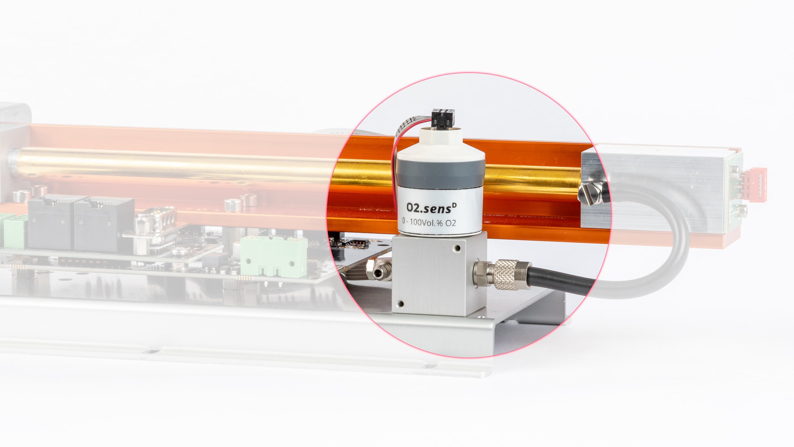
Übersicht
Spezifikationen
Allgemeine Merkmale
Version Standard Ausführung H2S resistente Ausführung Messbereich 0 – 25 Vol.% O2 0 – 100 Vol.% O2 0,5 – 35 Vol.% O2 Anwendung Biogas, KFZ-Abgasanalysator Industriell, vollständig CO2-beständig Industriell, vollständig CO2-beständig,
gute Beständigkeit gegenüber sauren GasenMedium-berührte Materialien ABS, FKM, PPS, PTFE, Edelstahl ABS, PVC, PPS, PTFE, Edelstahl ABS, PVC, PPS, PTFE,
EdelstahlErwartete Lebensdauer 1.000.000 Vol.% O2 h ~ 1.200.000 Vol.% O2 h ~ 1.200.000 Vol.% O2 h Lebensdauer des Sensors 4 Jahre bei Raumluft,
je nach Anwendung6 Jahre bei Raumluft,
je nach Anwendung6 Jahre bei Raumluft Abmessungen
(H x B x L)65,4 mm × 31,7 mm × 56,6 mm Gewicht 70 g Schlauchverbindung 4/6 mm Schlauch Messdaten *
Version Standard Ausführung H2S resistente Ausführung Messbereich 0 – 25 Vol.% O2 0 – 100 Vol.% O2 0,5 – 35 Vol.% O2 Auflösung 0,1 Vol.% 0,1 Vol.% 0,1 Vol.% Ansprechzeit (t90) < 3,5 s < 10 s < 5 s Drift ** < 1% pro Monat < 1% pro Monat < 3% pro Monat Linearitätsfehler 0 – 2 Vol.% O2: ± 0,1 abs.
2,1 – 100 Vol.% O2: ± 0,05 rel.0 – 2 Vol.% O2: ± 0,1 abs.
2,1 – 35 Vol.% O2: ± 0,05 rel.Wiederholgenauigkeit *** ± 1 Vol.% O2 ± 1 Vol.% O2 Einfluss von Luftfeuchtigkeit –0,03 % rel. O2-Messwert /
% RH–0,03 % rel. O2-Messwert /
% RH–0,03 % rel. O2-Messwert /
% RHQuerempfindlichkeit CO2: bis 20 Vol.%
CO: bis 2000 ppm
NOx: bis 5000 ppm
HC: bis 5000 ppm
N2O: bis 500 ppm< 20 ppm O2 bei:
100 Vol.% CO
100 Vol.% CO2
100 Vol.% C3H8
3000 ppm NO in N2
1000 ppm C6H6 in N2
500 ppm SO2 in N2
< 100 ppm O2 bei:
3000 ppm C2H6O
3000 ppm C4H10S
< 200 ppm O2 bei:
3000 ppm C2H6S2
< 400 ppm O2 bei:
100 Vol.% H2
< 500 ppm O2 bei:
2000 ppm H2S in N2< 20 ppm O2 bei:
100 Vol.% CO
100 Vol.% CO2
100 Vol.% C3H8
1000 ppm C6H6 in N2
2000 ppm H2S in N2
< 20000 ppm O2 bei:
3000 ppm NO in N2
1000 ppm H2 in N2
500 ppm SO2 in N2
** gemittelt über 12 Monate
*** @ 100 Vol.% O2 über einen Zeitraum von 5 minGas-Parameter
Version Standard Ausführung H2S resistente Ausführung Messbereich 0 – 25 Vol.% O2 0 – 100 Vol.% O2 0,5 – 35 Vol.% O2 Betriebstemperatur 0 – 40 °C
zeitweise 40 – 50 °C0 – 45 °C 0 – 50 °C Lagertemperatur -20 – 40 °C
5 – 25 °C empfohlen
40 – 50 °C max. 1 Woche5 – 30 °C empfohlen
-20 – 50 °C maximalLuftdruck 650 – 1250 hPa (mbar) 700 – 1250 hPa (mbar) 600 – 1250 hPa (mbar) Luftfeuchtigkeit 0 – 95% rel. Luftfeuchtigkeit (nicht kondensierend) Druck‐Sensor
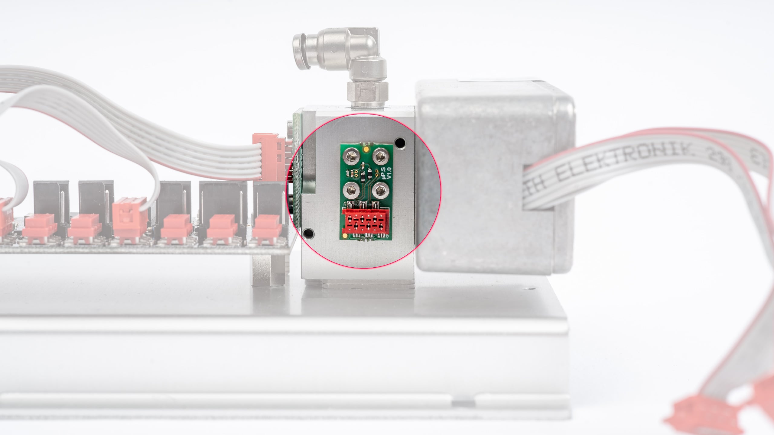
Übersicht
Spezifikationen
Feuchte‐Sensor
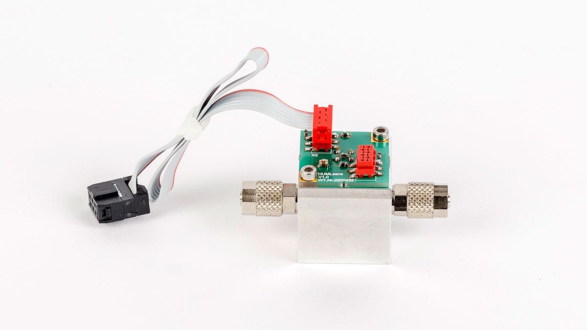
Übersicht
Spezifikationen
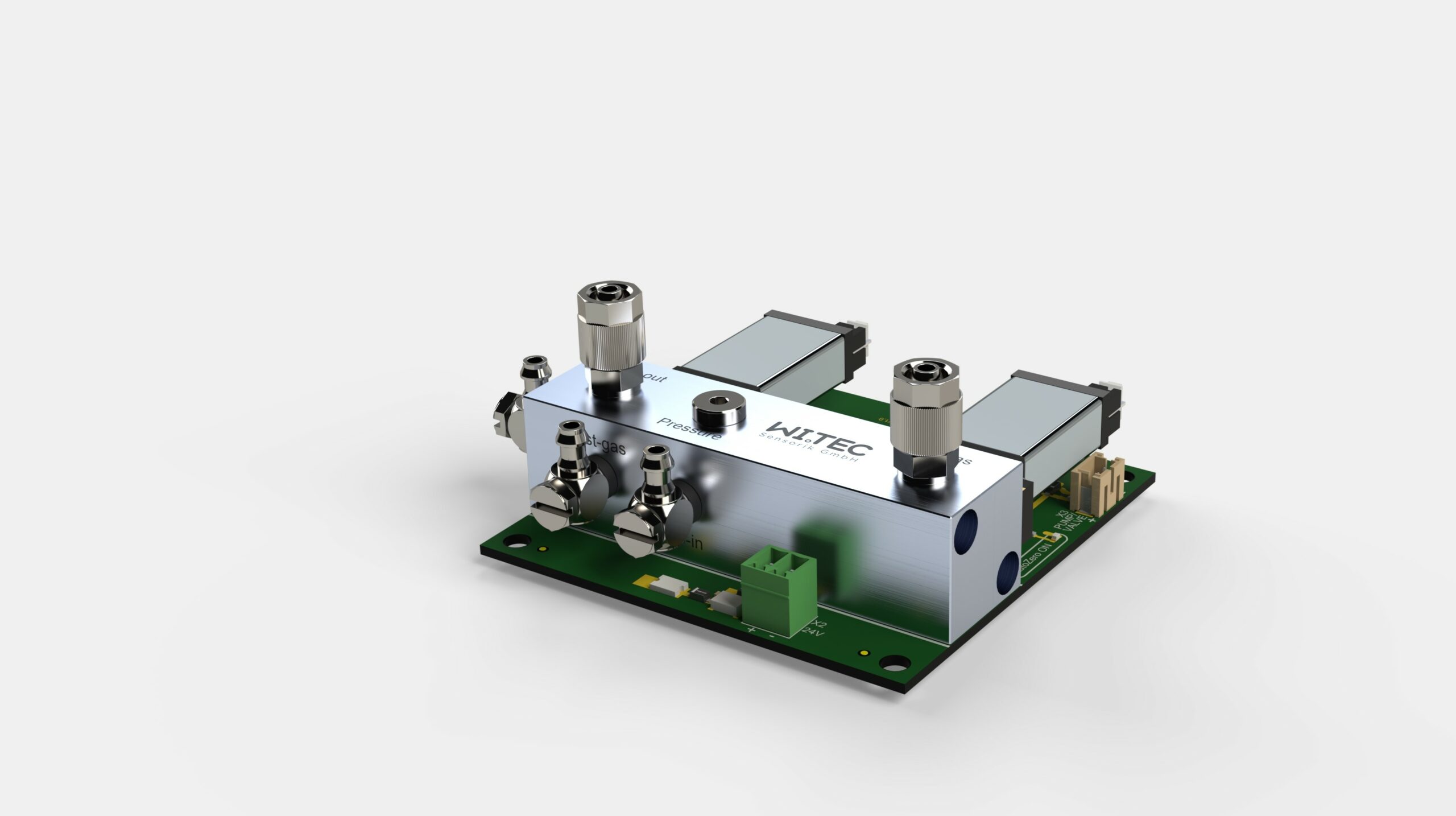
RITTER »MultiGas« Nullpunktabgleich-Modul (Luft)
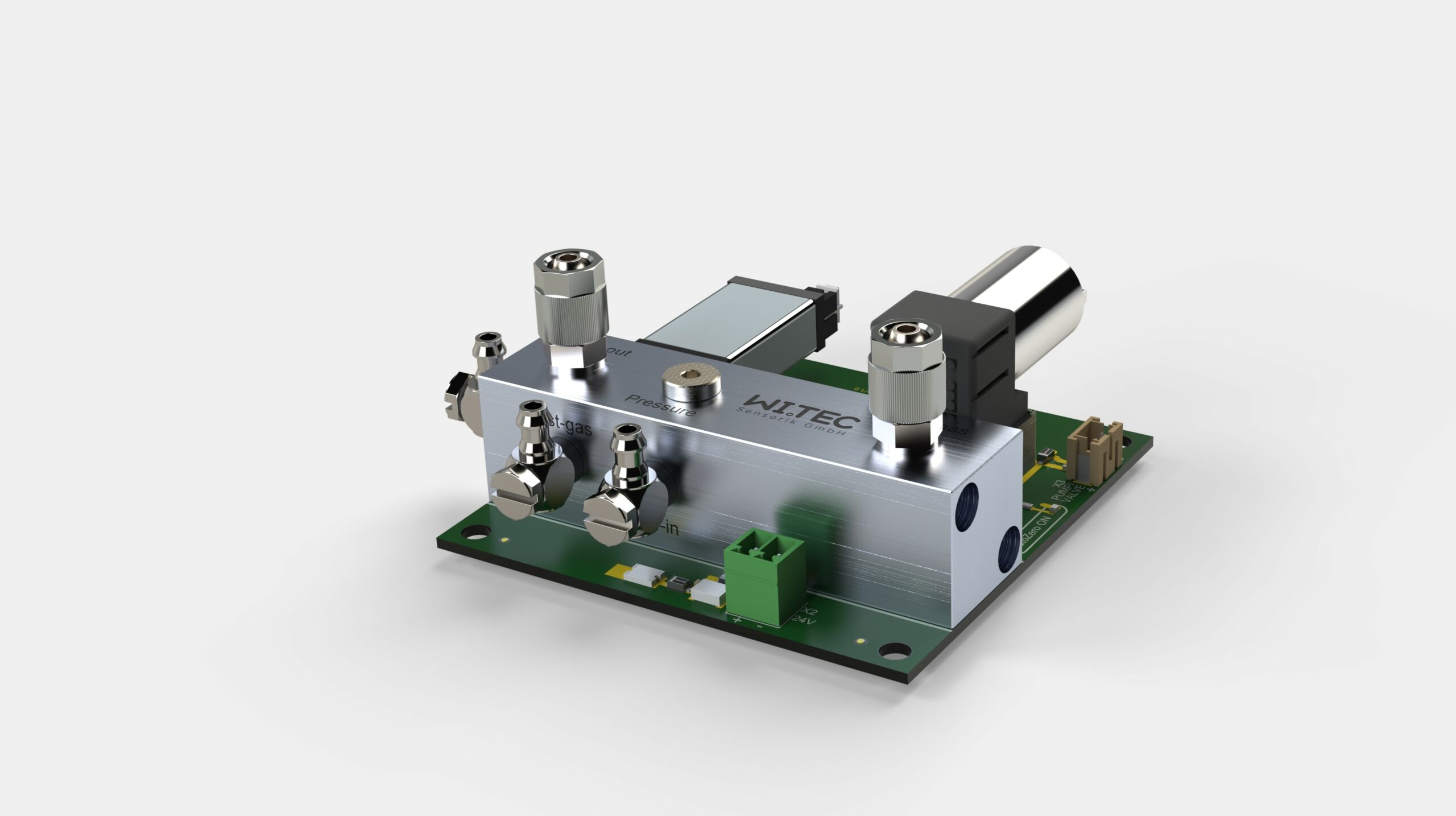
Übersicht
Merkmale
Spezifikationen
Druckabfall
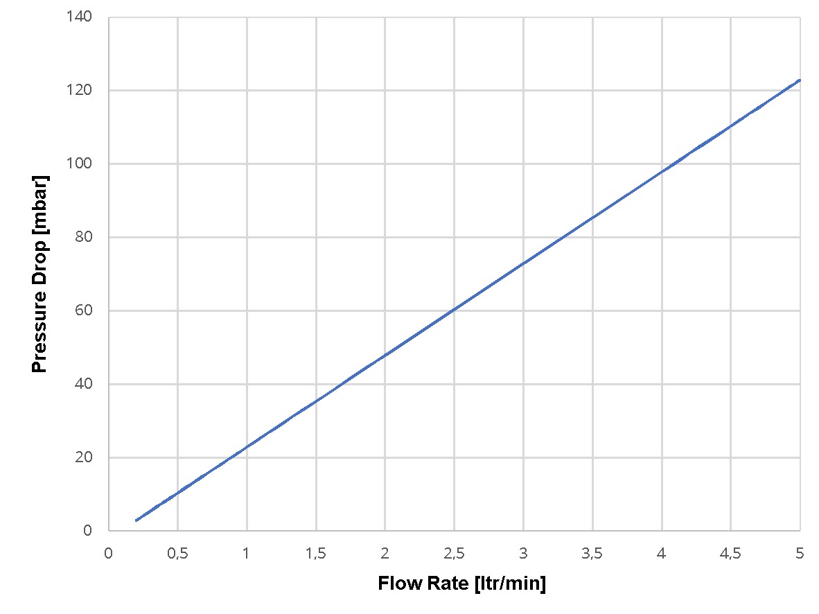
Schaltbild
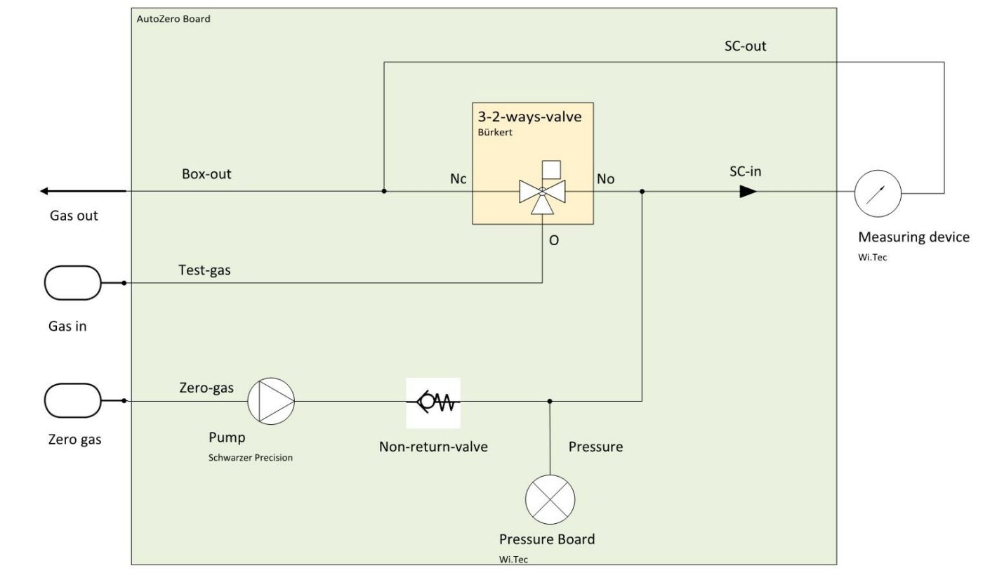
RITTER »MultiGas« Nullpunktabgleich-Modul (N2)
Übersicht
Merkmale
Spezifikationen
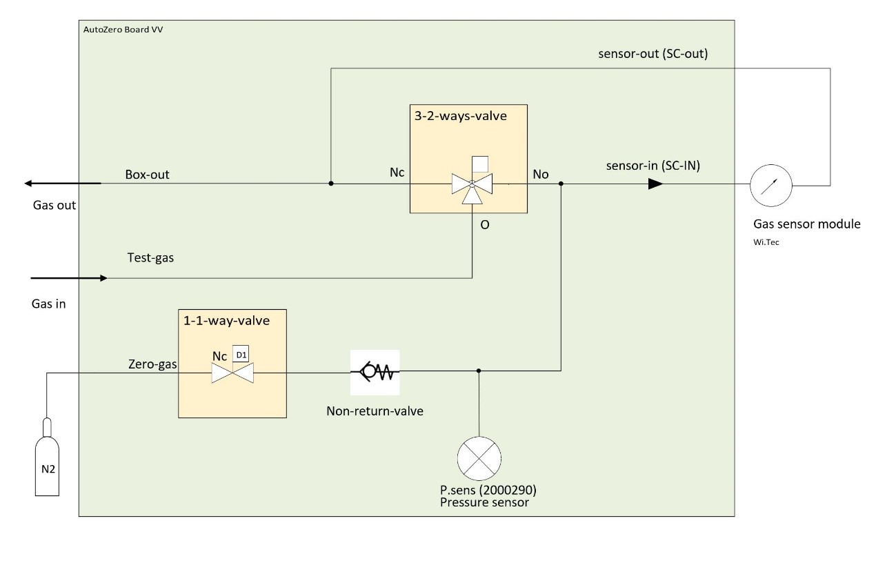
Druckabfall

Schaltbild
Analoger Spannungsausgang
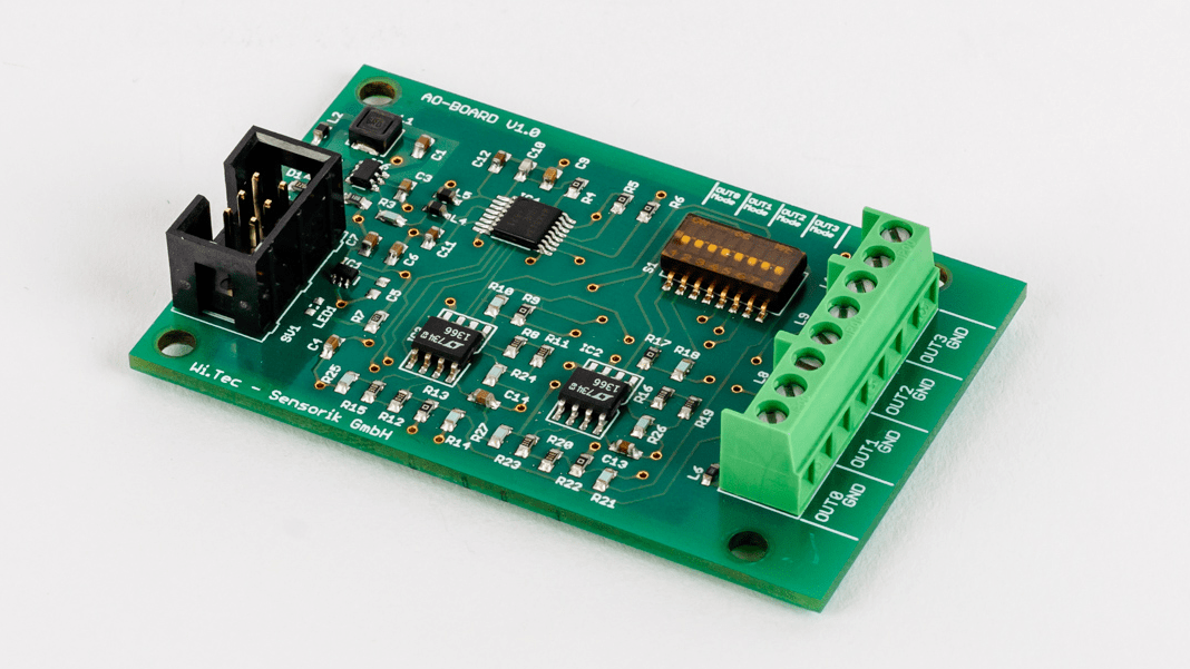
Übersicht
Technische Daten


Kontakt Nr. Zuordnung zu Kanal Aderfarben des mitgelieferten Verbindungs-Kabels 1 Kanal 1 weiß 2 Kanal 2 grün 3 Kanal 3 gelb 4 Kanal 4 grau 5 Masse braun Heizung und Thermostatisierung des Sensorgehäuses
Übersicht
Merkmale
Filter
Übersicht
Beschreibung
Anwendungen
Merkmale
Abmessungen
Spezifikationen
Allgemeine Merkmale
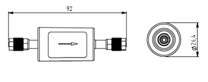
Abmessungen Ø 26,4 mm x 92 mm Gewicht 26 g Schlauchverbindung 4/6 mm Schlauch Volumenstrom 0 – 4 ltr/min Anwendung Partikel-Filter Gehäusevolumen 110 ml Medium-berührte Materialien Polyamid (Gehäuse), Edelstahl (Anschluss), FKM (O-Ring) Austausch-Intervall Abhängig von Gasverunreinigung Druckabfall (mbar) @ 1 ltr/min < 6 mbar Gas-Parameter
Betriebstemperatur -5 °C – 60 °C Lagertemperatur -20 °C – 110 °C Max. Druck 8 bar Luftfeuchtigkeit 0 – 95% relative Feuchte (nicht kondensierend) 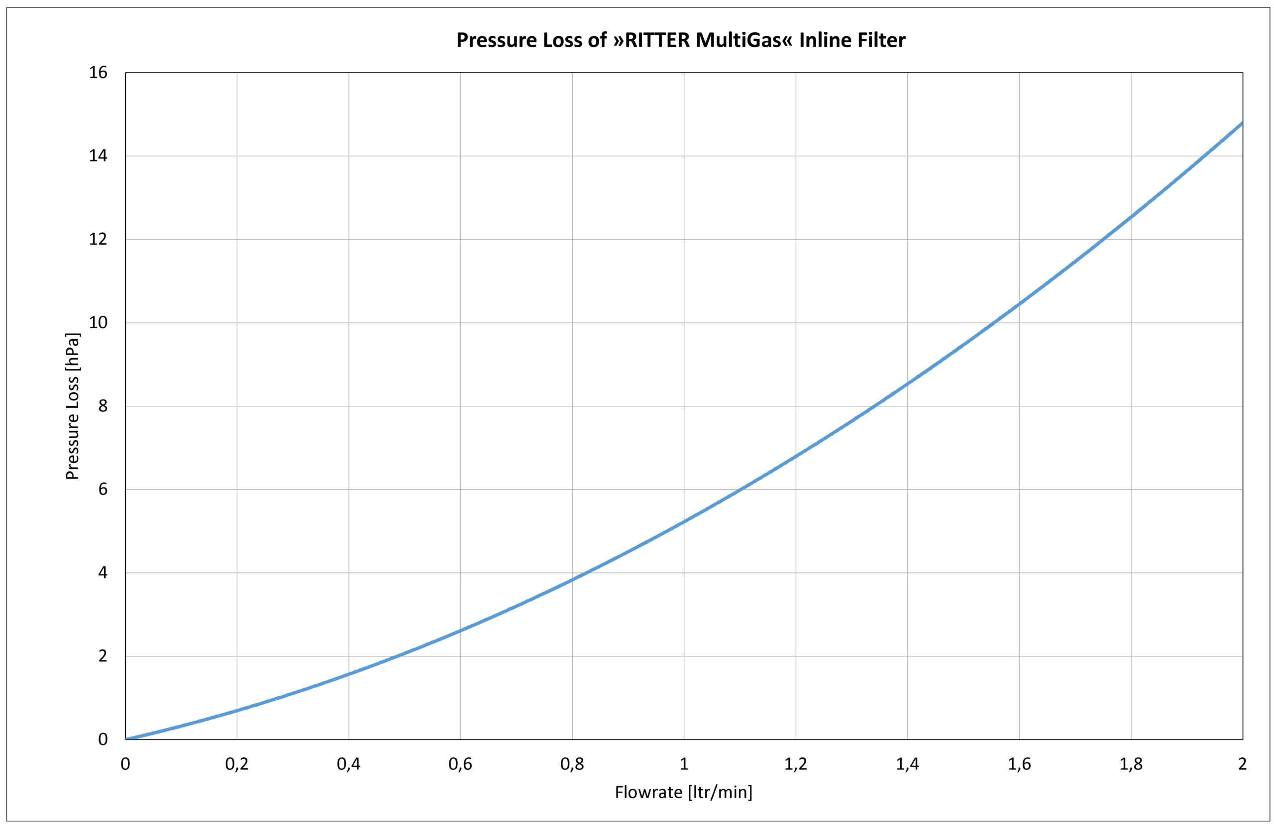
Pumpe für Gas-Probenahme

Übersicht
Anwendungen
Merkmale
Abmessungen

Spezifikationen
Allgemeine Merkmale
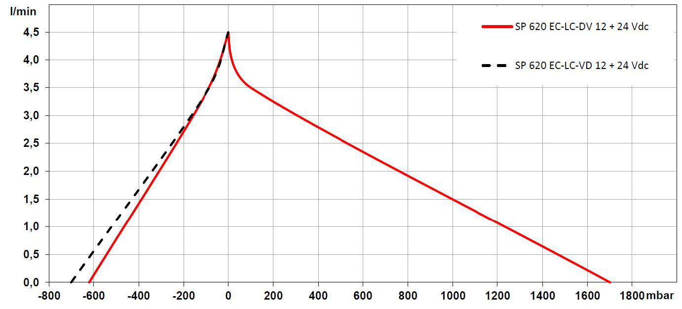
Betriebsspannung 24 VDC Max. Nennstrom 330 mA Pneumatischer Anschluss 4/6 mm Schlauch Volumenstrom 0 – 4,5 ltr/min Max. Druck 1,7 bar Maximales Vakuum -620 mbar Medium-berührte Materialien PVDF (Pumpenkopf)
PTFE (Diaphragma)
FFKM (Ventile und Dichtungen)Gewicht 184 g Abmessungen B x H x L 31 mm x 54 mm x 81,5 mm Gas-Parameter
Betriebstemperatur 5 °C – 50 °C Lagertemperatur -20 °C – 60 °C Luftfeuchtigkeit 0 – 95% rel. Luftfeuchtigkeit (nicht kondensierend) Leistungsdiagramm
