- 1 General Specifications
- 1.1 1.1. Casing Types
- 1.2 1.2. Dimensions
- 1.3 1.3. Assignment of Sensor Types to possible Sensor Combinations
- 1.3.1 Part 1: Pre‐configured SensorsIncl. casing type 1 with gas connection fittings, data port, power supply Ready for use
- 1.3.2 Part 2: Pre‐configured SensorsIncl. casing type 2 with gas connection fittings, data port, power supply Ready for use
- 1.3.3 Part 3: Individually combinable sensor modules Composition according Customer Specification Delivery incl. casing of suitable size according to number and type of modules Ready for use
- 1.3.4 Part 4: Casings for Sensor Modules assembled according to Customer Specification
- 1.3.5 Part 5 Built‐in Options
- 1.3.6 Part 6: Accessories / Options
- 2 Disadvantages of electrochemical (EC) sensors in comparison to the optical gas sensors RITTER »MultiGas«
- 3 Preventive / Protective Measures regarding the Gas to be measured
- 4 Scope of Supply
- 5 Setup
- 6 Infrared Sensors
- 7 Ultraviolet Sensors
- 8 可选配件 (installed inside of the sensor casing)
General Specifications
1.1. Casing Types


1.2. Dimensions
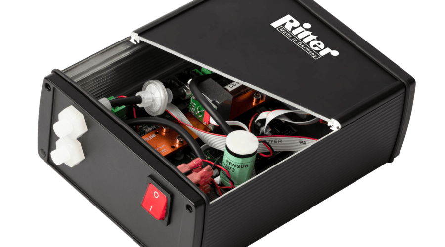
Casing Type 1 | Casing Type 2 | |
---|---|---|
A | 171 mm | 444 mm |
B | 290 mm (1) | 305 mm |
C | 86 mm | 145 mm |
Weight, approx. (2) | 2+ kg | 6.5 – 8 kg |
Connections gas in-/outlet | PVDF screw-type tube connection for tube Ø 4i / 6o mm | PVDF screw-type tube connection for tube Ø 4i / 6o mm |
Interfaces | USB ( Standard) / RS232 ( Option) | USB ( Standard) / RS232 ( Option) |
Power | 24 V DC | 24 V DC |
(2) Depending on type and number of built-in sensor modules
1.3. Assignment of Sensor Types to possible Sensor Combinations
- Part 1 – Pre‐configured sensors, incl. casing type 1 with gas connection fittings, data interface, plug‐in power supply – ready for use
- Part 2 – Pre‐configured sensors, incl. casing type 2 with gas connection glands, data interface, fittings, data interface, plug‐in power supply ‐ ready for use
- Part 3 – Individually combinable sensor modules, composition according to customer specification, delivery incl. housing in suitable size according to number and type of modules – ready for use
- Part 4 – Casings for sensor modules, assembled according to customer’s specification
- Part 5 – Built‐in options mounted inside of the casing
- Part 6 – Accessories / options
Part 1: Pre‐configured Sensors
Incl. casing type 1 with gas connection fittings, data port, power supply Ready for use
Sensor Type: RITTER MultiGas xxx | Article No. | Group of Gases IR | Number of Detectable Gases in this Group | Group of Gases UV | Number of Detectable Gases in this Group |
---|---|---|---|---|---|
xxx = mono IR1 | 2678 | CO2 CO N2O CH4 CnHm* CF4 SF6 H2O | 1 | ||
xxx = duo IR2 | 2742 | CO2 CO N2O CH4 CnHm* CF4 SF6 H2O | 2 | ||
xxx = trio IR3 | 2743 | CO2 CO N2O CH4 CnHm* CF4 SF6 H2O | 3 | ||
xxx = mono UV1 | 2749 | O3 Cl2 ≤ 5% SO2 NO2 | 1 | ||
xxx = mono UV1 Cl2 30% | 2763 | Cl2 ≤ 30% | 1 | ||
xxx = duo UV2 | 2766 | O3 Cl2 ≤ 5% SO2 NO2 | 2 | ||
xxx = duo IR1 + UV1 | 2797 | CO2 CO N2O CH4 CnHm* CF4 SF6 H2O | 1 | O3 Cl2 ≤ 5% SO2 NO2 | 1 |
xxx = trio IR1 + UV2 | na | CO2 CO N2O CH4 CnHm* CF4 SF6 H2O | 1 | O3 Cl2 ≤ 5% SO2 NO2 | 2 |
Part 2: Pre‐configured Sensors
Incl. casing type 2 with gas connection fittings, data port, power supply Ready for use
Sensor Type: RITTER MultiGas xxx | Article No. | Group of Gases IR | Number of Detectable Gases in this Group | Group of Gases UV | Number of Detectable Gases in this Group |
---|---|---|---|---|---|
xxx = mono UV1 H2S ≤ 5.000 ppm | 2672 | H2S ≤ 5.000ppm | 1 | ||
xxx = mono UV1 H2S ≤ 1% | 2855 | H2S ≤ 1% | 1 | ||
xxx = UVRAS | 2812 | SO2 NO2 NO | 1 | ||
xxx = duo IR1 + H2S ≤ 5000 ppm | 2959 | CO2 CO N2O CH4 CnHm* CF4 SF6 H2O | 1 | H2S | 1 |
xxx = duo IR1 + (H2S ≤1% / NO) | 2960 | CO2 CO N2O CH4 CnHm* CF4 SF6 H2O | 1 | H2S ≤ 1% NO | 1 |
Part 3: Individually combinable sensor modules
Composition according Customer Specification
Delivery incl. casing of suitable size according to number and type of modules Ready for use
Sensor Type: RITTER MultiGas xxx | Article No. | Group of Gases IR | Number of Detectable Gases in this Group | Group of Gases UV | Number of Detectable Gases in this Group |
---|---|---|---|---|---|
xxx = Mod IR1 | 2813 | CO2 CO N2O CH4 CnHm* CF4 SF6 H2O | 1 | ||
xxx = Mod IR2 | 2814 | CO2 CO N2O CH4 CnHm* CF4 SF6 H2O | 2 | ||
xxx = Mod IR3 | 2815 | CO2 CO N2O CH4 CnHm* CF4 SF6 H2O | 3 | ||
xxx = Mod UV1 | 2830 | O3 Cl2 ≤ 5% SO2 NO2 | 1 | ||
xxx = Mod UV1 Cl2 30% | na | Cl2 ≤ 30% | 1 | ||
xxx = Mod UV1 H2S ≤ 5.000 ppm | 2841 | H2S | 1 | ||
xxx = Mod UV1 H2S ≤ 1% | 2856 | H2S | 1 | ||
xxx = Mod UV2 | 2831 | O3 Cl2 ≤ 5% SO2 NO2 | 2 | ||
xxx = Mod UVRAS | 2917 | SO2 NO2 NO | 3 |
Part 4: Casings for Sensor Modules assembled according to Customer Specification
Casing Type: RITTER MultiGas xxx | Article No. | Casing Type | Suitable for |
---|---|---|---|
xxx = Cas-2 (1) | 2817 | Casing type 2 | … multiple modules up to 444 x 145 x 305 mm |
xxx = Cas-3 (1) | 2818 | Casing type 3 | … multiple modules up to 464 x 189 x 305 mm |
Part 5 Built‐in Options
Option Type: RITTER MultiGas xxx | Article No. | Name | 测量范围 |
---|---|---|---|
xxx = O2 (2) (3) | 2767 | Oxgen Sensor | 0 – 100% |
xxx = O2-resist (3) | 2824 | Oxygen Sensor, H2S resistant | 0.5 – 35% |
xxx = P (2) (3) | 2771 | Pressure Sensor | 800 – 1200 mbar abs.[/wpml-string] / Resolution <1 mbar |
xxx = P-resist (3) | 2825 | Pressure Sensor, H2S resistant | 0.2 – 3.5 bar abs. / Resolution 2 mbar |
xxx = H (2) (3) | 2773 | Humidity Sensor | 0 – 100% RH |
xxx = A/O | 2648 | Analog Voltage Output 0-2V / 0-5V / 0-10V | 4 Analog output ports for 4 separate gas concentrations, 16 bit |
xxx = Therm-Cas | 2954 | Thermostated Casing | Heating and thermostatting of the sensor casing at 50°C |
(2) Not suitable for SO2, Cl2, H2S
(3) Available as supplement to IR or UV sensor only
Part 6: Accessories / Options
Option Type: RITTER MultiGas xxx | Article No. | Name | Range |
---|---|---|---|
xxx = Cal-ZP-N2 | 2805 | Calibration Gas N2 | For zero-point calibration of all gases |
xxx = Flow-V | 2806 | Mini Flow Valve | Control of flow rate, incl. Manometer for calibration gas bottle |
xxx = Cal-CG-Cat1 | 2948 | Calibration with special carrier gas (Ar, H2, He) for gases category 1 | Category 1 gases: CO2 CO < 0Vol-% N2O CH4 CnHm* CF4 SF6 O3 CL2 SO2 < 10Vol-% NO2 NO |
xxx = Cal-CG-Cat2 | 2949 | Calibration with special carrier gas (Ar, H2, He) for gases category 2 | Category 2 gases: CO > 10Vol-% H2S SO2 > 10Vol-% |
xxx = Cal-ReCal-Cat1 | 2950 | Calibration for gases category 1 | Category 1 gases: CO2 CO < 0Vol-% N2O CH4 CnHm* CF4 SF6 O3 CL2 SO2 < 10Vol-% NO2 NO |
xxx = Cal-ReCal-Cat2 | 2951 | Calibration for gases category 2 | Category 2 gases: CO > 10Vol-% H2S SO2 > 10Vol-% |
红外模块 NDIR 紫外线模块 NDUV 紫外线模块 NDUV / UVRAS
* 用丙烷校准
Disadvantages of electrochemical (EC) sensors in comparison to the optical gas sensors RITTER »MultiGas«
Preventive / Protective Measures regarding the Gas to be measured
Important: Please specify the desired options when ordering
a) Additional tube connection for flushing of the casing
The gas lines inside the casing and the measuring cuvette are gas-tight by means of O-rings and other gas-tight connections. However, as with all connections, a leakage rate, however slight, cannot be ruled out. With an additional tube connection for flushing of the casing, an accumulation of the measuring gas inside the casing can be prevented.
In the case of toxic or aggressive gases, a suction line can be connected via this tube connection, which creates a under-pressure inside the housing thus preventing the gas from escaping from the casing.
In case of ignitable gases (methane, hydrogen, etc.), a pressure or suction line can be connected via this tube connection creating an over- or under-pressure inside the casing thus preventing the accumulation of an ignitable gas mixture.
请注意: H2S can be perceived as an unpleasant smell even in the ppb range. Even with an O-ring seal, micro-leaks can occur, which can be extracted by flushing the housing.
b) Heated and thermostatted casing
A condensation of the measuring gas inside of the sensor must be prevented. This is done in general for example by a condensation trap or gas cooler.Alternatively, the inside of the sensor casing can be heated and thermostatted at 50°C (standard). The heating not only avoids condensation inside of the sensor but ensures constant measurement results as well.
c) Particle filter
Please make sure by use of a suitable filter that no particles are carried into the sensor. These might block the small orifices of the internal fittings. It is recommended to use filters of 5 micron or smaller.
Scope of Supply
No. of Items | Item |
---|---|
1 | Document folder including : Calibration Certificate / 数据表 / Software Manual |
1 | Sensor in table top casing |
1 | Power adapter |
1 | Data acquisition software (on USB memory card) 1 USB connection cable (sensor computer ) |
3m | Viton tubing Øi 4mm/Øo 6mm |
Setup
- Unpack all items carefully
- Install the data acquisition software according to the “RITTER MultiGas Software Manual”.
Don’t start the software at this point in time. - Place the sensor next to the gas source
请注意: A tube connection between gas source and sensors that is as short as possible allows a small dead space created by the tubing. In turn, a small dead space enables a fast response time of the sensor. - Connect the power adapter to socket “DC 24 V” at the rear side of the sensor and to mains.
- Connect the data acquisition cable to the respective socket at the rear side of the sensor and to the computer:
- USB cable to the socket “USB”
- RS232 cable to the socket “RS 232” (选项 )
- Connect the gas source to the gas inlet port of the sensor by using the provided tubing as follows:
- Unscrew the screw cap from the gas inlet port.
- Slide the screw cap onto the end of the tube with the thread of the screw cap facing the tube end.
- Push the tube onto the cone in the center of the gas inlet port.
- Slide the screw cap to the gas inlet port and screw it hand-tightly in place.
- 如果适用:将传感器的气体出口连接到其他组件,例如气体采样袋、排气管等。
- Switch-on the power switch at the front side of the sensor casing.
- Start the software and open the COM port(s) of the connected sensor module(s) according to the software manual.
The RITTER »MultiGas« Sensor is now ready for use.
Infrared Sensors
描述
Gas analysis based on the NDIR technique is an established method to determine the concentrations of gases in complex mixtures. The RITTER »MultiGas« sensors use new optical components for optimal analysis results: Up to 3 optical filters analyse the gas which flows through the sensor as one gas stream. The optional oxygen, pressure, and humidity sensors are in-line with the same single gas stream.
The individual internal modules are sealed by means of O-ring connections.
In order to achieve an optimum adaptation to the required measuring range, the lengths of the modular measurement cells (= cuvettes) can be implemented in the range of 5 mm (large measurement range in percentage level) up to 250 mm (small measurement range in ppm level).
Cuvettes with a length ≥ 20 mm are coated with a resistant gold layer in order to improve the reflection properties for low concentration level detection. Cuvettes used with aggressive gases are gold-coated as well.
The other internal mechanical parts are made out of aluminium, optionally out of stainless steel.
For fast response applications the measuring system delivers a stable result within t90 ≈ 3 seconds.
The entire unit can be disassembled for easy maintenance/service.
应用程序
Specifications

General features
Measurement technology: | Innovative NDIR Sensor (non-dispersive infrared sensor) |
Detectable gases: | CO2 CO N2O CH4 CnHm* CF4 SF6 H2O |
Number of simultaneously detectable gases: | max. 3 per sensor unit |
Measurement ranges: | See below |
Flow rate range: | 5 ~ 300 ltr/h – For higher flow rates the sensor can be operated in bypass |
Max. gas inlet pressure: | 300 mbar |
Pressure loss (without additional optional sensors): | 10 @ 100 / 35 @ 200 / 70 @ 300 (mbar @ ltr/h) |
Temperature compensation: | Yes |
Data acquisition software: | Yes |
Lifetime of IR radiation source: | > 40 000 h |
Measurement cuvette: | Aluminium, with measurement ranges ≤1% gold-plated inside |
Cuvette sealing: | Viton O-ring |
套管: | High-quality table-top casing, aluminium |
Dimensions (W x H x L): | 171 x 86 x 290 mm |
重量: | approx. 2 kg |
Gas connections: | PVDF screw-type tube connection for tube Øi 4mm, Øo 6 mm |
Measuring response
Linearity error: | < ± 1% F.S. |
Repeatability: | ± 0.5% F.S. |
Long term stability zero: | < ± 2% F.S. / week |
Long term stability span: | < ± 2% F.S. / month |
Temperature influence of zero point: | < 1% F.S. / 10K |
Temperature influence of span: | < 2% F.S. / 10K |
Cross sensitivity: | < 2% F.S. |
Pressure influence: | < 1.5% / 10hPa of reading |
Warm-up time: | 2 min |
Response time (t90): | ≈ 3 sec |
Sampling frequency by software: | ≤ 10 Hz |
Detection limit: | See below |
Resolution: | 0.5 x detection limit |
Water vapour: | No influence with measurements of CO2 and CH4 |
Electrical features
Power supply: | 24 VDC incl. power plug 100 ~ 240 VAC / 24 VDC |
Average power consumption: | < 1W |
Interface: | USB (standard), RS232 (选项) – incl. data transmission cable 1 m |
Analogue voltage output (选项): | 0-2V / 0-5V / 0-10V |
Climatic conditions
Operating temperature: | +15 ~ +45 °C |
Storage temperature: | –20 ~ +60 °C |
Operating pressure: | 800 ~ 1200 hPa (mbar) |
Ambient humidity: | 0 ~ 95% rel. humidity // Condensing inside of sensor must be prevented! |
* Analysis of CnHm*
The calibration of sensors for CnHm will be performed with propane. Aromatic hydrocarbons are also measured but with a different weighting. This means that the sensitivity of the sensor is significantly smaller with these gases than with other hydrocarbons.
测量范围表
测量范围 / 满分值 (F.S.) | |||||||||||||||
---|---|---|---|---|---|---|---|---|---|---|---|---|---|---|---|
100 Vol.% | 50 Vol.% | 30 Vol.% | 20 Vol.% | 10 Vol.% | 5 Vol.% | 1 Vol.% | 5,000 ppm | 2,000 ppm | 1,000 ppm | 500 ppm | 300 ppm | 100 ppm | 50 ppm | 10 ppm | |
CO2 | |||||||||||||||
CO | |||||||||||||||
N2O | |||||||||||||||
CH4 | |||||||||||||||
CnHm* | |||||||||||||||
CF4 | |||||||||||||||
SF6 | |||||||||||||||
H2O | 根据要求提供测量范围 |
红外模块 NDIR 紫外线模块 NDUV 紫外线模块 NDUV / UVRAS
* 用丙烷校准
Table of Detection Limits (= 3 σ) in Percent of Full Scale
检测限 / 满刻度值的百分比 (F.S.) | |||||||||||||||
---|---|---|---|---|---|---|---|---|---|---|---|---|---|---|---|
100 Vol.% | 50 Vol.% | 30 Vol.% | 20 Vol.% | 10 Vol.% | 5 Vol.% | 1 Vol.% | 5,000 ppm | 2,000 ppm | 1,000 ppm | 500 ppm | 300 ppm | 100 ppm | 50 ppm | 10 ppm | |
CO2 | < 0.1% | < 0.1% | < 0.1% | < 0.1% | < 0.1% | < 0.1% | < 0.1% | < 0.1% | < 0.1% | < 0.1% | < 0.3% | < 0.3% | |||
CO | < 0.2% | < 0.2% | < 0.2% | < 0.2% | < 0.2% | < 0.2% | < 0.2% | < 0.3% | < 0.5% | < 0.5% | |||||
N2O | < 0.1% | < 0.1% | < 0.1% | < 0.1% | < 0.1% | < 0.1% | < 0.1% | < 0.3% | |||||||
CH4 | < 0.1% | < 0.1% | < 0.1% | < 0.1% | < 0.1% | < 0.1% | < 0.1% | < 0.3% | < 0.5% | ||||||
CnHm* | < 0.1% | < 0.1% | < 0.1% | < 0.2% | < 0.2% | < 0.2% | < 0.2% | < 0.5% | < 0.5% | ||||||
CF4 | < 0.2% | < 0.2% | < 0.2% | ||||||||||||
SF6 | < 0.1% | < 0.1% | < 0.1% | < 0.2% | < 0.5% | < 0.3% | < 0.3% | ||||||||
H2O | 根据要求提供测量范围 |
红外模块 NDIR 紫外线模块 NDUV 紫外线模块 NDUV / UVRAS
* 用丙烷校准
检测限的定义
检测极限是在特定的不确定度下可以获得的最小的测量值。这个不确定性包括气体传感器对特定气体和特定测量范围的分辨率、噪音和稳定性。为了评估检测极限值,需要在相同的测量条件下进行多次单次测量。根据获得的单次测量结果,计算出标准偏差 "Sigma"(σ)。表中给出的数值等于Sigma的三倍量。
Recalibrations
The following recalibration intervals are recommended for IR sensors:
Ultraviolet Sensors
描述
The RITTER »MultiGas« UV sensor is the world’s first gas analysis module based on miniaturized UV-LEDs. The stability and lifetime of these UV-LEDs enables high-precision gas analyses down to the ppm range. By using two UV-LEDs two gases can be detected simultaneously. Furthermore, with this approach measuring ranges from ppm to Vol.-% can be realized.
In the spectral range from 200 nm to 500 nm, nitrogen oxides (NO + NO2), aromatic hydrocarbons, hydrogen sulphide, ozone, sulphur dioxide and chlorine can be reliably detected with this new sensor platform.
The entire unit can be disassembled for easy maintenance/service.
The individual internal modules are sealed by means of O-ring connections.
In order to achieve an optimum adaptation to the required measuring range, the lengths of the modular measurement cells (= cuvettes) can be implemented in the range of 5 mm (large measurement range in percentage level) up to 250 mm (small measurement range in ppm level).
Cuvettes with a length ≥ 20 mm are coated with a resistant gold layer in order to improve the reflection properties for low concentration level detection. Cuvettes used with aggressive gases are gold-coated as well.
The internal mechanical parts are made out of aluminium, optionally out of stainless steel.
For fast response applications the measuring system delivers a stable result within t90 ≈ 1-2 seconds.
应用程序
Specifications NDUV Sensor

General features
Measurement technology: | Innovative NDUV Sensor (non-dispersive ultraviolet sensor) |
Detectable gases: | O3 CL2 H2S SO2 NO2 |
Number of simultaneously detectable gases: | max. 2 |
Measurement ranges: | See below |
Flow rate range: | 1 ltr/d ~ 300 ltr/h – For higher flow rates the sensor can be operated in bypass |
Max. gas inlet pressure: | 300 mbar |
Pressure loss (without additional optional sensors): | 10 @ 100 / 35 @ 200 / 70 @ 300 (mbar @ ltr/h) |
Temperature compensation: | Yes |
Data acquisition software: | Yes |
Lifetime of UV radiation source: | > 8 000 h |
Measurement cuvette: | Stainless steel with silicone coating inside |
Cuvette sealing: | Viton O-ring |
套管: | High-quality table-top casing, aluminium |
Dimensions (W x H x L): | 464 x 189 x 305 mm |
重量: | approx. 6.5+ kg |
Gas connections: | PVDF screw-type tube connection for tube Øi 4mm, Øo 6 mm |
Measuring response
Linearity error: | < ± 1% F.S. |
Repeatability: | ± 0.5% F.S. |
Long term stability zero N2: | < ± 1% F.S. / 24h |
Long term stability span: | < ± 1% F.S. / month |
Temperature influence of zero point: | < 1% F.S. / 10K |
Temperature influence of span: | < 2% F.S. / 10K |
Cross sensitivity: | < 2% F.S. |
Pressure influence: | < 1.5% / 10hPa of reading[/wpml-string] |
Warm-up time: | 1 min (initial), <60 min for full specification |
Response time (t90): | 1.5 – 15 sec[/wpml-string] |
Sampling frequency by software: | ≤ 10 Hz |
Detection limit: | See below |
Resolution: | 0.5 x detection limit |
Electrical features
Power supply: | 24 VDC incl. power plug[/wpml-string] 100 ~ 240 VAC / 24 VDC |
Supply current (peak[/wpml-string]) | <0.4 A |
Average power consumption | < 7.5 W |
Interface: | USB (standard), RS232 (option) – incl. data transmission cable 1 m |
Analogue voltage output (option[/wpml-string]): | 0-2V / 0-5V / 0-10V |
Climatic conditions
Operating temperature: | +25 ~ +45 °C |
Storage temperature: | –20 ~ +60 °C |
Operating pressure: | 800 ~ 1200 hPa (mbar) |
Ambient humidity: | 0 ~ 95% rel. humidity // Condensing inside of sensor must be prevented! |
Specifications H2S Sensor

The H2S sensor works according to the principle of non-dispersive UV absorption (NDUV).
The measuring wavelength used is in the lower nanometer range, which enables inter-ference-free measurements with water vapour and hydrocarbons. This makes the sensor ideal for use in biogas measurements, as accompanying gases such as NH3, CO2, CH4 and H2O do not affect the accuracy of the measurements.
General features
Measurement technology: | Innovative NDUV Sensor (non-dispersive ultraviolet sensor) Dual beam |
Detectable gases: | H2S SO2 |
Number of simultaneously detectable gases: | max. 2 |
Measurement ranges: | See below |
Flow rate range: | 6 ~ 300 ltr/h – For higher flow rates the sensor can be operated in bypass |
Max. gas inlet pressure: | 300 mbar |
Pressure loss (without additional optional sensors): | 10 @ 100 / 35 @ 200 / 70 @ 300 (mbar @ ltr/h) |
Temperature compensation: | Yes |
Data acquisition software: | Yes |
Lifetime of UV radiation source: | > 8 000 h |
Measurement cuvette: | Stainless steel with silicone coating inside |
Cuvette sealing: | Viton O-ring |
套管: | High-quality table-top casing, aluminium |
Dimensions (W x H x L): | 464 x 189 x 305 mm |
重量: | approx. 6.5+ kg |
Gas connections: | PVDF screw-type tube connection for tube Øi 4mm, Øo 6 mm |
Measuring response
Linearity error: | < ± 1% F.S. |
Repeatability: | ± 0.5% F.S. |
Long term stability zero N2: | < ± 1% F.S. / 24h |
Long term stability span: | < ± 1% F.S. / month |
Temperature influence of zero point: | < 1% F.S. / 10K |
Temperature influence of span: | < 2% F.S. / 10K |
Cross sensitivity: | < 2% F.S. |
Pressure influence: | < 1.5% / 10hPa of reading |
Warm-up time: | 1 min (initial), < 15 min for full specification |
Response time (t90): | 1.5 – 15 sec |
Sampling frequency by software: | ≤ 10 Hz |
Detection limit: | See below |
Resolution: | 0.5 x detection limit |
Electrical features
Power supply: | 24 VDC incl. power plug 100 ~ 240 VAC / 24 VDC |
Supply current (peak): | <0.4 A |
Average power consumption: | < 7.5 W |
Interface: | USB (standard), RS232 (选项) – incl. data transmission cable 1 m |
Analogue voltage output (选项): | 0-2V / 0-5V / 0-10V |
Climatic conditions
Operating temperature: | +5 ~ +45 °C |
Storage temperature: | –20 ~ +60 °C |
Operating pressure: | 800 ~ 1200 hPa (mbar) |
Ambient humidity: | 0 ~ 95% rel. humidity // Condensing inside of sensor must be prevented! |
Specifications UVRAS Sensor

For the detection of NO an EDL (electrodeless gas discharge lamp) is used. In the EDL, N2 and O2 are converted to NO and produce a selective UV radiation. With this radiation, a cross-sensitivity-free NO measurement is made possible. This method is called UV resonance absorption spectroscopy (UVRAS).
A combination of both the UVRAS and NDUV technology allows the simultaneous gas analysis of NO, NO2 and SO2 in the lower ppm range which is particularly important in flue gas analysis (Continuous Emission Monitoring, CEM).
General features
Measurement technology: | Innovative NDIR Sensor (non-dispersive infrared sensor) |
Detectable gases: | SO2 NO2 NO |
Number of simultaneously detectable gases: | max. 3 per sensor unit |
Measurement ranges: | See below |
Flow rate range: | 1 ltr/d ~ 300 ltr/h – For higher flow rates the sensor can be operated in bypass |
Max. gas inlet pressure: | 300 mbar |
Pressure loss (without additional optional sensors): | 10 @ 100 / 35 @ 200 / 70 @ 300 (mbar @ ltr/h) |
Temperature compensation: | Yes |
Data acquisition software: | Yes |
Lifetime of IR radiation source: | > 40 000 h |
Measurement cuvette: | Aluminium, with measurement ranges ≤1% gold-plated inside |
Cuvette sealing: | Viton O-ring |
套管: | High-quality table-top casing, aluminium |
Dimensions (W x H x L): | 171 x 86 x 290 mm |
重量: | approx. 2 kg |
Gas connections: | PVDF screw-type tube connection for tube Øi 4mm, Øo 6 mm |
Measuring response
Linearity error: | < ± 1% F.S. |
Repeatability: | ± 0.5 % F.S. |
Long term stability zero N2: | < 3 ppm / 24h |
Long term stability span: | < ± 1 % F.S. / month |
Temperature influence of zero point: | < 1 % F.S. / 10 K |
Temperature influence of span: | < 2 % F.S. / 10 K |
Cross sensitivity: | |
Pressure influence: | < 1.5% / 10 hPa of reading |
Warm-up time: | 1 min (initial), < 60 min for full specification |
Response time (t90): | 1.5 ~ 15 sec |
Sampling frequency by software: | ≤ 10 Hz |
Detection limit: | See below |
Resolution: | 0.5 x detection limit |
Electrical features
Power supply: | 24 VDC incl. power plug 100 ~ 240 VAC / 24 VDC |
Supply current (peak): | 1.5 A |
Inrush current: | 0.2 ~ 0.7 A |
Power consumption: | 36 W |
Interface: | USB (standard), RS232 (选项) – incl. data transmission cable 1 m |
Analogue voltage output (option[/wpml-string]): | 0-2V / 0-5V / 0-10V |
Climatic conditions
Operating temperature: | +5 ~ +40 °C |
Storage temperature: | –20 ~ +60 °C |
Operating pressure: | 800 ~ 1200 hPa (mbar) |
Ambient humidity: | 0 ~ 95% rel. humidity // Condensing inside of sensor must be prevented! |
测量范围表
测量范围 / 满分值 (F.S.) | |||||||||||||||
---|---|---|---|---|---|---|---|---|---|---|---|---|---|---|---|
100 Vol.% | 50 Vol.% | 30 Vol.% | 20 Vol.% | 10 Vol.% | 5 Vol.% | 1 Vol.% | 5,000 ppm | 2,000 ppm | 1,000 ppm | 500 ppm | 300 ppm | 100 ppm | 50 ppm | 10 ppm | |
O3 | |||||||||||||||
CL2 | |||||||||||||||
H2S | |||||||||||||||
SO2 | |||||||||||||||
NO2 | |||||||||||||||
NO |
红外模块 NDIR 紫外线模块 NDUV 紫外线模块 NDUV / UVRAS
* 用丙烷校准
(1) Full Scale (FS)
Other ranges on request
Table of Detection Limits (= 3 σ) in Percent of Full Scale
检测限 / 满刻度值的百分比 (F.S.) | |||||||||||||||
---|---|---|---|---|---|---|---|---|---|---|---|---|---|---|---|
100 Vol.% | 50 Vol.% | 30 Vol.% | 20 Vol.% | 10 Vol.% | 5 Vol.% | 1 Vol.% | 5,000 ppm | 2,000 ppm | 1,000 ppm | 500 ppm | 300 ppm | 100 ppm | 50 ppm | 10 ppm | |
O3 | < 0.1% | < 0.1% | < 0.1% | < 0.2% | < 0.5% | < 0.5% | < 0.5% | ||||||||
CL2 | < 0.1% | < 0.1% | < 0.1% | < 0.1% | < 0.1% | < 0.1% | < 0.1% | < 0.2% | < 0.5% | ||||||
H2S | < 0.1% | < 0.1% | < 0.1% | < 0.1% | < 0.2% | < 0.5% | |||||||||
SO2 | < 0.1% | < 0.1% | < 0.1% | < 0.1% | < 0.1% | < 0.1% | < 0.1% | < 0.1% | < 0.5% | < 0.5% | < 0.5% | ||||
NO2 | < 0.1% | < 0.1% | < 0.1% | < 0.2% | < 0.2% | < 0.5% | < 0.5% | < 0.5% | |||||||
NO | < 0.1% | < 0.1% | < 0.1% | < 0.2% | < 0.2% |
红外模块 NDIR 紫外线模块 NDUV 紫外线模块 NDUV / UVRAS
* 用丙烷校准
检测限的定义
检测极限是在特定的不确定度下可以获得的最小的测量值。这个不确定性包括气体传感器对特定气体和特定测量范围的分辨率、噪音和稳定性。为了评估检测极限值,需要在相同的测量条件下进行多次单次测量。根据获得的单次测量结果,计算出标准偏差 "Sigma"(σ)。表中给出的数值等于Sigma的三倍量。
1) Zero to Full Scale (FS)
Recalibrations
The following recalibration intervals are recommended for UV sensors:
可选配件 (installed inside of the sensor casing)
8.1. 氧传感器
除了 RITTER MultiGas NDIR 或 NDUV 传感器之外,氧气传感器是一个可选的传感器模块。 测得的氧气浓度显示在提供的软件中。 有两个版本可用:

a) 非腐蚀性气体规范
测量技术: | 电化学传感器 |
测量范围 (标准版本): | 0 – 25% or 0 – 100% |
测量精度: | ±2% 跨度(满量程) |
决议: | < 0.5% 跨度(满量程) |
响应时间 (t90): | ≈ 15 s; 汽车版 ≈ 5 s |
终身: | 约5年 |
b) H2S和类似酸性气体的规格
测量技术: | 电化学传感器 |
测量范围 (H2S 耐用版本): | 0.5 – 35% |
测量精度: | ±2% 跨度(满量程) |
决议: | < 0.5% 跨度(满量程) |
响应时间 (t90): | ≈ 15 s; 汽车版 ≈ 5 s |
终身: | 约5年 |
8.2. 压力传感器
气体压力的变化导致每体积分子数的变化,从而导致气体密度的变化。这种密度变化反过来又对传感器的浓度测量结果有很大影响。通过测量样品池(比色皿)内的气体压力,对浓度测量值进行补偿/校正。
压力传感器是一个传感器模块,可作为RITTER MultiGas NDIR或NDUV传感器的附加选项。测量的压力值显示在提供的软件中。有两个版本可供选择。

a) 非腐蚀性气体规范
测量范围: | 800 – 1,200 mbar 绝对的 |
测量精度: | ±1% 跨度(满量程) |
决议: | <1 mbar |
响应时间 (t90): | 1 s |
包括温度补偿 |
b) H2S和类似酸性气体的规格
测量范围: | 0.2 – 3.5 bar 绝对的 |
测量精度: | ±1% 跨度(满量程) |
决议: | 2 mbar |
响应时间 (t90): | 1 s |
包括温度补偿 |
8.3. 湿度传感器
湿度传感器是一个传感器模块,可作为RITTER MultiGas NDIR或NDUV传感器的附加选项。测量的湿度值(绝对值和相对值)会在提供的软件中显示。
规格
测量技术: | 聚合物湿度传感器 |
测量范围: | 0-100% rH |
测量精度: | ±2% rH 跨度(满量程) |
决议: | ±1% RH |
响应时间 (t90): | 12 s |
包括温度补偿 | |
指示值(在软件中): | 绝对的 (% absH) 和相对湿度 (% rH) |

8.4. 模拟电压输出
对于与模拟数据采集设备的连接,模拟电压输出端口可提供以下电压水平。
电压范围是根据订单预设的,用户不能改变。
模拟电压输出模块允许在4个独立的通道同时输出多达4个不同的数值。
请注意: 将各自的气体浓度测量值分配给各个通道。这些分配在传感器单元的校准协议中说明。

在模拟电压输出的插座和插头上为气体浓度测量的通道分配触点。


联系号码 | 分配给通道 | 电缆的电线颜色 |
---|---|---|
1 | 渠道 1 | 白色 |
2 | 渠道 2 | 绿色 |
3 | 渠道 3 | 黄色 |
4 | 渠道 4 | 灰色 |
5 | ground | 棕色 |
连接电缆在交付时带有明线,可与用户的模拟数据采集设备连接。
8.5. 传感器外壳的加热和恒温处理
为了避免潮湿的气体在传感器内部凝结,可以对传感器外壳进行加热和恒温处理。作为标准配置,温度控制器预设为50°C;可根据要求提供更低的温度。
加热元件和温度控制器被安装在测量比色皿的支架上。

规格
温度控制器 | 30-50°C |
控制精度 | ± 0,2 K |
加热功率 | 12 Watt / 30 带外部加热元件的瓦特 |