- 1 Especificaciones generales
- 1.1 Tipos de carcasa
- 1.2 Dimensiones & Especificaciones
- 1.3 Asignación de tipos de sensores a posibles combinaciones de sensores
- 1.3.1 Pieza 1: Sensores preconfigurados incl. tipo de carcasa 1
- 1.3.2 Pieza 2: Sensores preconfigurados incl. tipo de carcasa 2
- 1.3.3 Pieza 3: Módulos de sensores combinables individualmente
- 1.3.4 Pieza 4: Carcasas para módulos sensores
- 1.3.5 Pieza 5: Opciones integradas
- 1.3.6 Pieza 6: Accesorios / Opciones
- 1.4 Calibraciones
- 1.5 Measurement of Humid Gases
- 2 Desventajas de los sensores electroquímicos (EC) en comparación con los sensores ópticos »MultiGas« de RITTER
- 3 Medidas preventivas y de protección con mediciones de gas
- 4 Alcance del suministro
- 5 Instalar
- 6 Sensores de Infrarrojos
- 7 Sensores Ultravioleta
- 8 Opciones (instalado en el interior de la carcasa del sensor)
- 8.1 Sensor de oxigeno
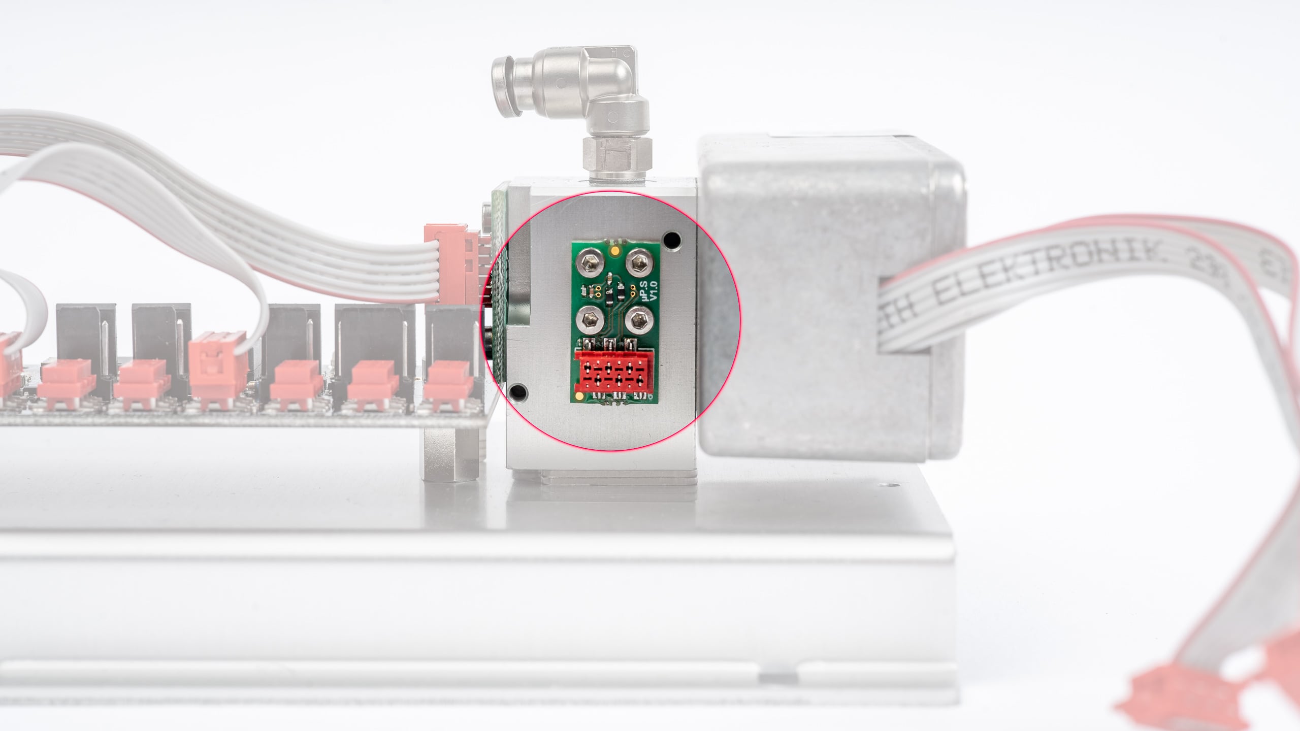
- 8.2 Sensor de presión
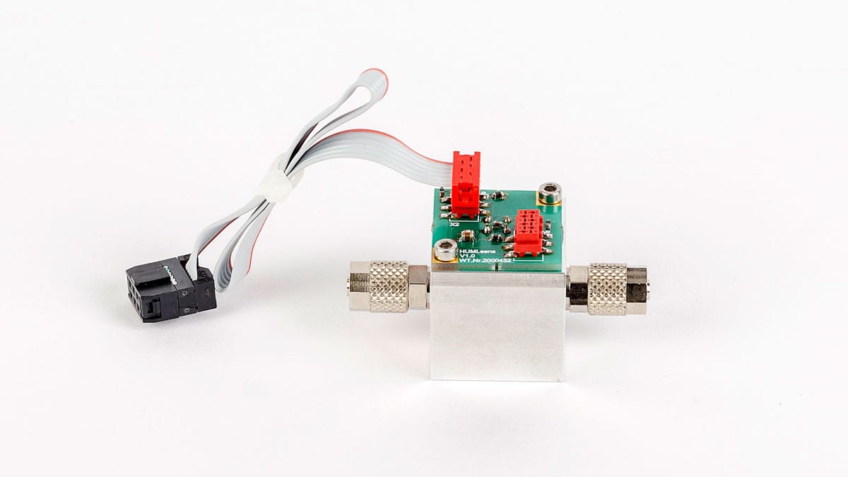
- 8.3 Sensor de humedad
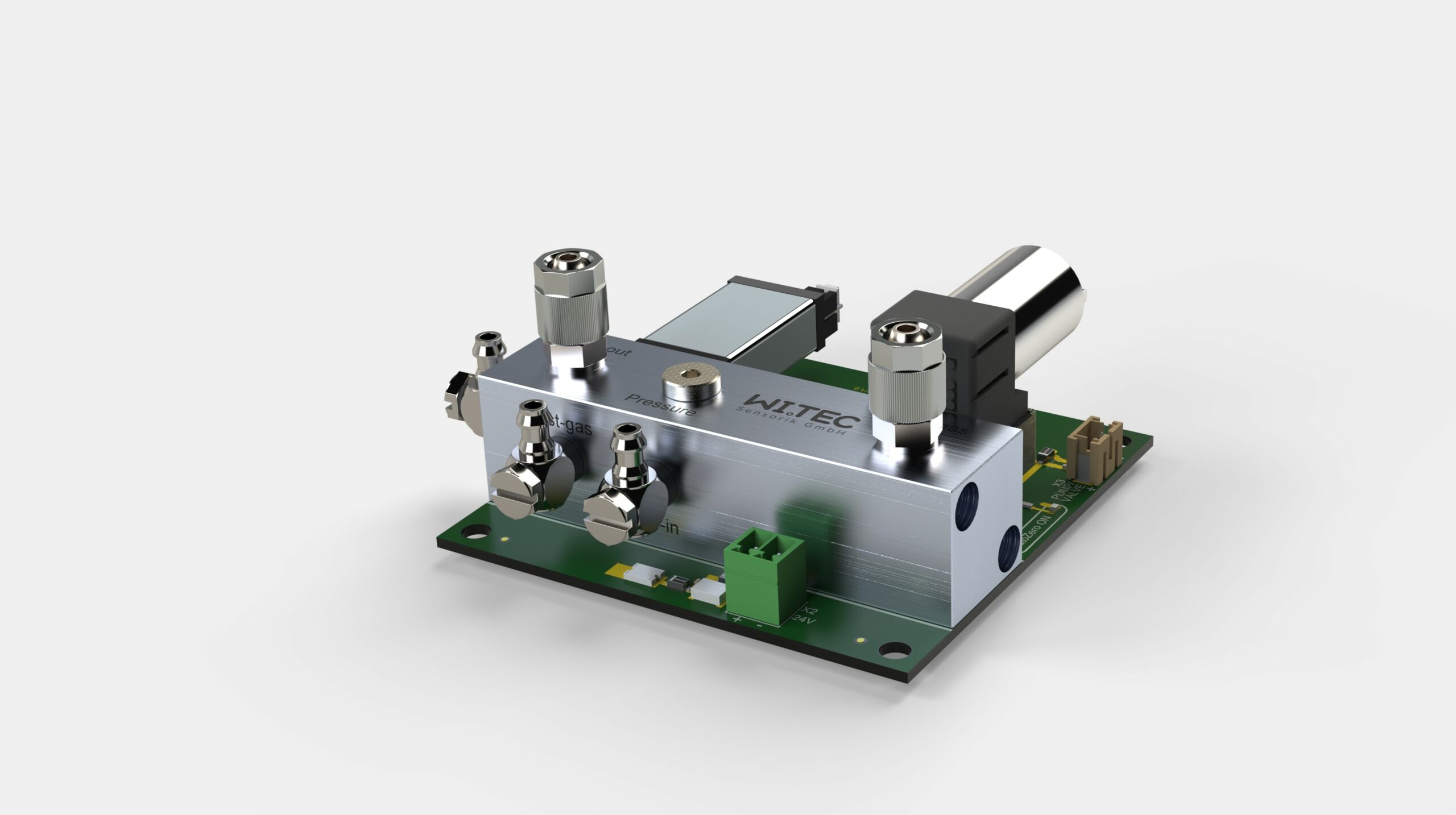
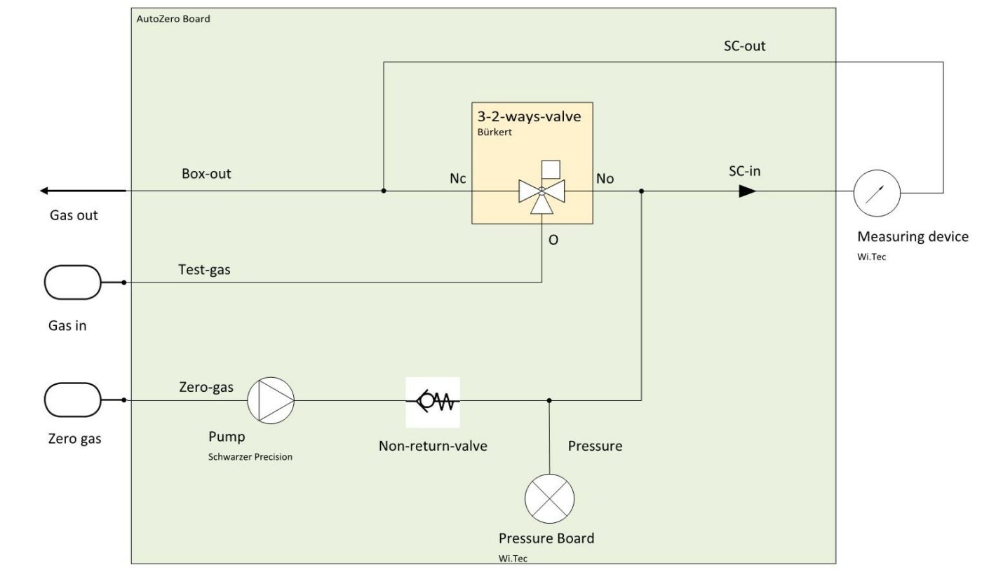
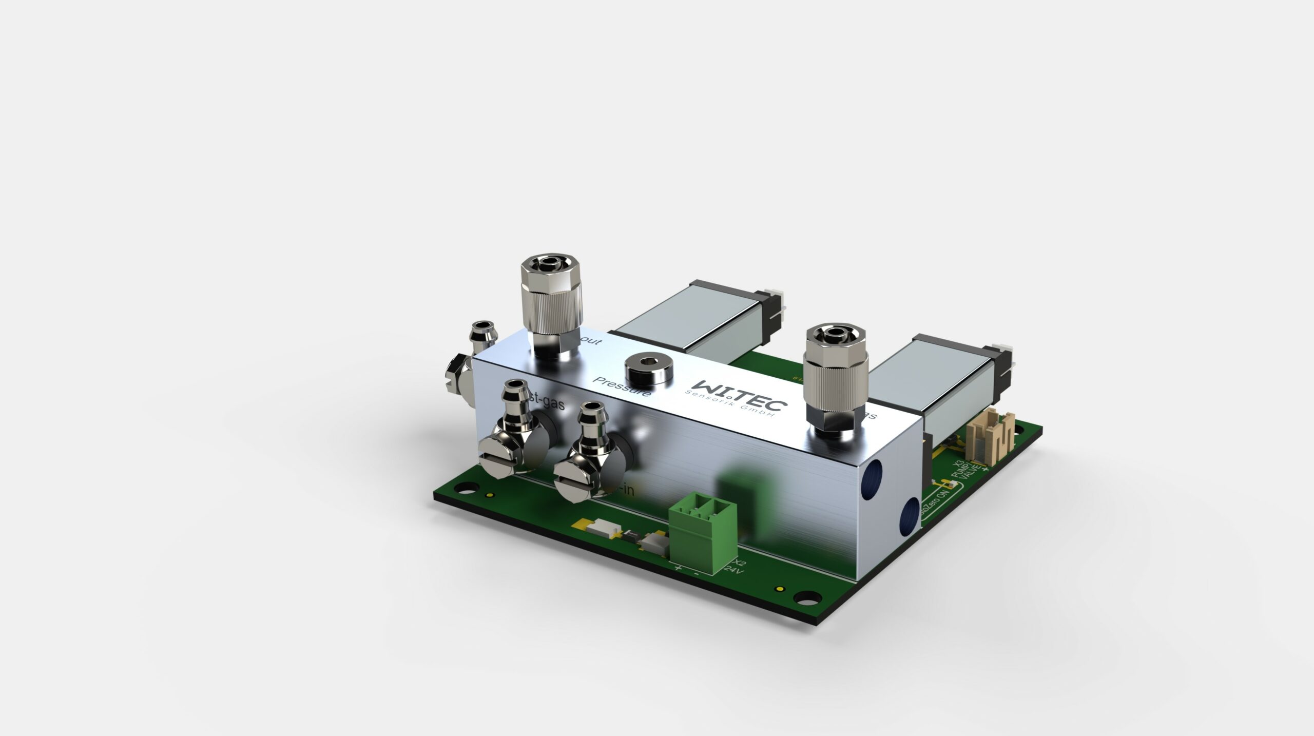
- 8.4 RITTER »MultiGas« Módulo de ajuste del punto cero (Aire)
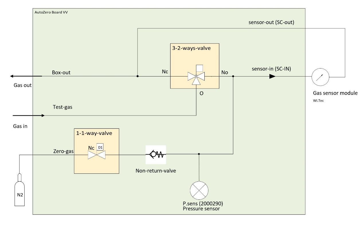
- 8.5 RITTER »MultiGas« Módulo de ajuste del punto cero (N2)
- 8.6 Salida de tensión analógica
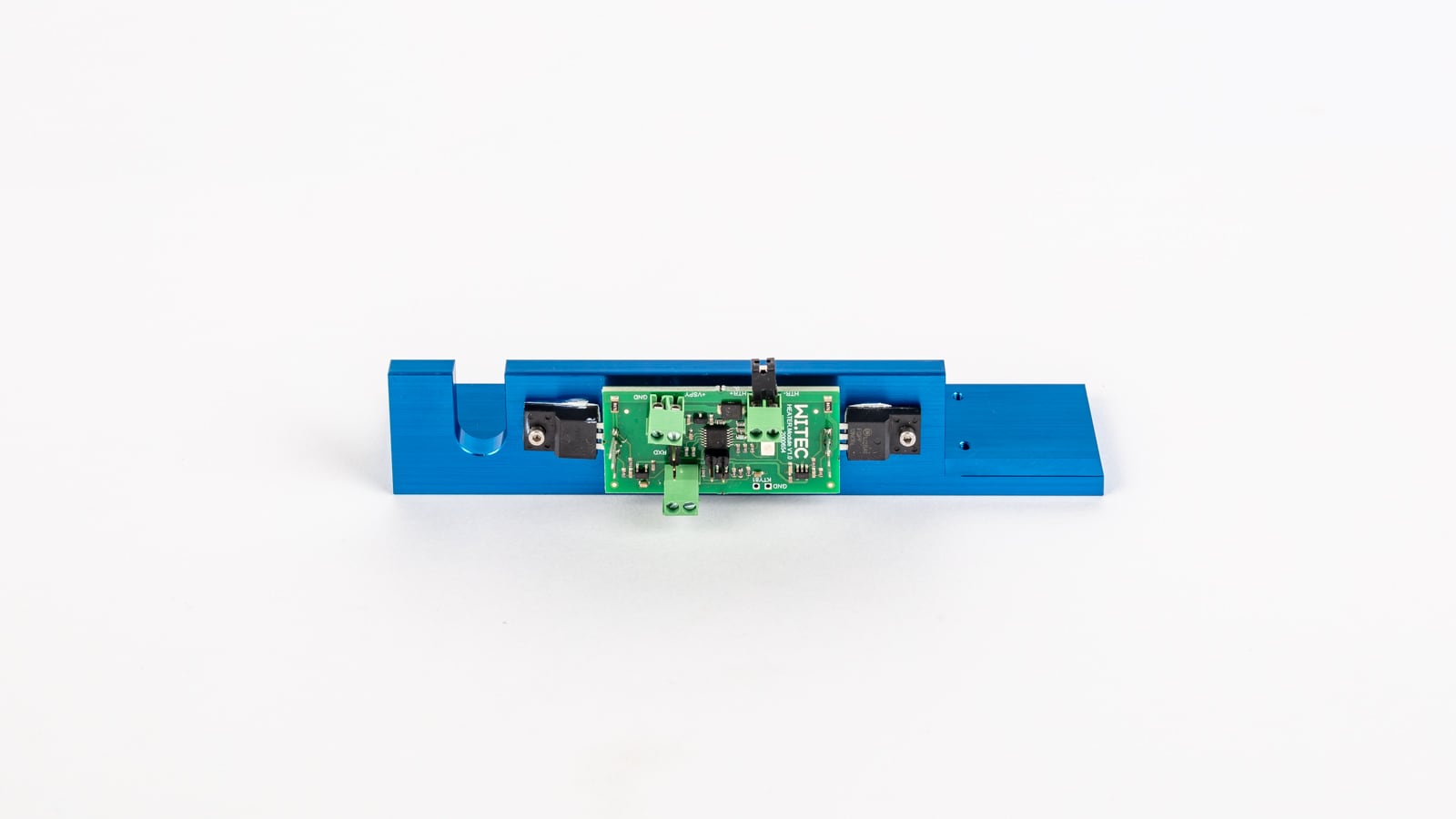
- 8.7 Calentamiento y termofijación de la carcasa del sensor
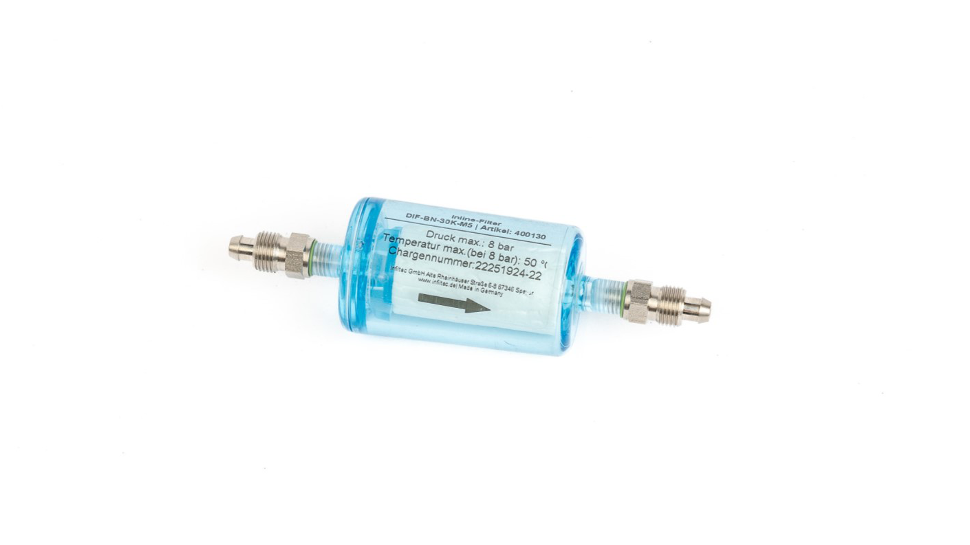
- 8.8 Filtro
- 8.9 Bomba de muestreo de gas
Especificaciones generales
Tipos de carcasa


Dimensiones & Especificaciones
Tipo de carcasa 1 Tipo de carcasa 2 A 171 mm 444 mm B 290 mm (1) 305 mm C 86 mm 145 mm Peso, aprox. (2) 2+ kg 6,5 – 8 kg Conexiones entrada/salida de gas Conexión roscada de PVDF para tubo Ødentro 4 mm, Øfuera 6 mm Tubo de conexión PVC Rauclair Ødentro 4 mm, Øfuera 6 mm, 3 m Interfaces USB (estándar), RS232 / CANbus / CANopen (opciones), MODbus a petición Alimentación 24 VDC, incl. fuente de alimentación enchufable
100 – 240 VAC, 50/60 Hz
(2) En función del tipo y el número de módulos sensores incorporados
Especificaciones de la interfaz
USB
- Tipo: USB 2.0
- Conector: Tipo B
- Cable de conexión: Tipo B /
tipo A
RS232
- Tipo: RS232
- Conector: D-sub9 hembra
- Cable de conexión: D-sub9 1:1 enchufe/enchufe
CANopen
- Tipo de protocolo: Modo CANopen 2
- Velocidad de transmisión: 250 kBaud
- Node ID: 0x31
- Conector: RJ45
CANbus
- Tipo de protocolo: Modo CANbus 1 (no estándar)
- Velocidad de transmisión: 250 kBaud
- ID de transmisión: 0x208
- Recibir ID: 0x300
- Conector: RJ45
MODbus
- Velocidad de transmisión: 250 kBaud
- Databits: 8
- Stopbit: 1
- Parity: None
- Float Definition: IEE754
- Registros disponibles:
- Read Holding Register 0x03
- Read Input Register 0x04
- Write Single Register 0x06
- Conector: RJ45
Asignación de tipos de sensores a posibles combinaciones de sensores
Pieza 1: Sensores preconfigurados incl. tipo de carcasa 1
With gas connection fittings, data interface, plug-in power supply - ready for use
Tipo de sensor:
RITTER MultiGas xxxArtículo
No.Grupo de gases
IRNúmero de gases detectables
en este GrupoGrupo de gases
UVNúmero de gases detectables
en este Grupo xxx = mono IR1 2678 1 xxx = duo IR2 2742 2 xxx = trio IR3 2743 3 xxx = mono UV1 2749 1 xxx = mono UV1
Cl2 30%2763 1 xxx = duo UV2 2766 2 xxx = duo IR1 + UV1 2797 1 1 xxx = trio IR1 + UV2 na 1 2
Pieza 2: Sensores preconfigurados incl. tipo de carcasa 2
With gas connection fittings, data interface, plug-in power supply - ready for use
Tipo de sensor:
RITTER MultiGas xxxArtículo
No.Grupo de gases
IRNúmero de gases detectables
en este GrupoGrupo de gases
UVNúmero de gases detectables
en este Grupo xxx = mono UV1
H2S ≤ 5000 ppm2672 1 xxx = mono UV1
H2S ≤ 1%2855 1 xxx = UVRAS 2812 1 xxx = duo IR1
+ H2S ≤ 5000 ppm2959 1 1 xxx = duo IR1
+ (H2S ≤ 1% / NO)2960 1 1
Pieza 3: Módulos de sensores combinables individualmente
Composición según especificación del cliente, entrega incl. carcasa en tamaño adecuado según número y tipo de módulos - listo para usar
Tipo de sensor:
RITTER MultiGas xxxArtículo
No.Grupo de gases
IRNúmero de gases detectables
en este GrupoGrupo de gases
UVNúmero de gases detectables
en este Grupo xxx = Mod IR1 2813 1 xxx = Mod IR2 2814 2 xxx = Mod IR3 2815 3 xxx = Mod UV1 2830 1 xxx = Mod UV1
Cl2 30%na 1 xxx = Mod UV1
H2S ≤ 5000 ppm2841 1 xxx = Mod UV1
H2S ≤ 1%2856 1 xxx = Mod UV2 2831 2 xxx = Mod UVRAS 2917 3
Pieza 4: Carcasas para módulos sensores
Ensamblado según las especificaciones del cliente
Tipo de carcasa:
RITTER MultiGasArtículo
No.Tipo de carcasa Adecuado para xxx = Cas-2 (1) 2817 Tipo de carcasa 2 Módulos múltiples de hasta 444 x 305 x 145 mm xxx = Cas-3 (1) 2818 Tipo de carcasa 3 Módulos múltiples de hasta 444 x 305 x 189 mm
Pieza 5: Opciones integradas
Tipo de opción:
RITTER MultiGasArtículo
No.Descripción Rango de medición RMS-O2 (2) (3) 2795 Sensor de oxigeno 0 ‐ 25% RMS-O2 (2) (3) 2767 Sensor de oxigeno 0 – 100% RMS-O2-resist (3) 2824 Sensor de oxigeno
H2S resistente0,5 – 35% RMS-P (2) (3) 2771 Sensor de presión 800 – 1200 mbar abs.
Resolución <1 mbar RMS-P-resist (3) 2825 Sensor de presión
H2S resistente0,2 – 3,5 bar abs.
Resolución 2 mbar RMS-H (2) (3) 2773 Sensor de humedad 0 – 100% RH RMS-A/O 2648 Salida de tensión analógica
0-2 V / 0-5 V / 0-10 V4 puertos de salida analógica para 4 concentraciones de gas distintas
16 bit RMS‐CasHeat 2954 Carcasa con termostato Calentamiento y termostatación de la carcasa del sensor a 45 °C
(3) Disponible sólo como complemento del sensor IR o UV
Pieza 6: Accesorios / Opciones
Tipo de opción:
RITTER MultiGas xxxArtículo
No.Descripción Rango de medición xxx = Cal-ZP-N2 2805 Gas de calibración N2 Para la calibración del punto cero de todos los gases xxx = Flow-V 2806 Miniválvula de caudal Control del caudal de la botella de gas de calibración
Manómetro incluido xxx = Cal-CG-Cat1 2948 Calibración con gas portador especial (Ar, H2, He)
para gases de categoría 1Gases de categoría 1:
xxx = Cal-CG-Cat2 2949 Calibración con gas portador especial (Ar, H2, He)
para gases de categoría 2Gases de categoría 2:
xxx = Cal-ReCal-Cat1 2950 Recalibrado para gases de categoría 1 Gases de categoría 1:
xxx = Cal-ReCal-Cat2 2951 Recalibrado para gases de categoría 2 Gases de categoría 2:
Módulo de infrarrojos NDIR Módulo ultravioleta NDUV
Calibraciones
En función del número de gases que se vayan a analizar, deberá seleccionarse un gas de calibración adecuado. Además, el tipo de gas también influye en el gas de calibración óptimo. Debido al número casi infinito de combinaciones posibles, la siguiente lista sólo debe entenderse como una primera visión general.
Measurement of Humid Gases
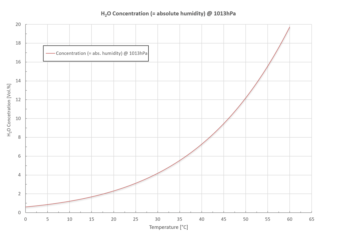
Cuando se miden gases húmedos, es esencial evitar la condensación del vapor de agua en el interior del sensor. El siguiente diagrama muestra la concentración máxima de vapor de agua ( = humedad absoluta) en % en volumen en función de la temperatura a la presión estándar 1013 mbar.
El diagrama muestra:
La condensación puede evitarse con las siguientes medidas:
Con el sensor de humedad opcional se puede medir la humedad relativa en el rango de medición de 0 ~ 100% rH. Además, también se puede medir la humedad absoluta en g/m³. Ambos valores se muestran en el software suministrado.
Desventajas de los sensores electroquímicos (EC) en comparación con los sensores ópticos »MultiGas« de RITTER
Medidas preventivas y de protección con mediciones de gas
Importante: Especifique las opciones deseadas al realizar el pedido
a) Conexión de tubo adicional para el lavado de la carcasa
Los conductos de gas del interior de la carcasa y la cubeta de medición son estancos al gas mediante juntas tóricas y otras conexiones estancas al gas. Sin embargo, como ocurre con todas las conexiones, no se puede descartar una tasa de fugas, por pequeña que sea. Con una conexión de tubo adicional para el lavado de la cubeta se puede evitar una acumulación del gas de medición dentro de la cubeta.
En el caso de gases tóxicos o agresivos, se puede conectar una línea de aspiración a través de esta conexión de tubo, que crea una subpresión dentro de la carcasa impidiendo así que el gas salga de la carcasa.
En caso de gases inflamables (metano, hidrógeno, etc.), se puede conectar una línea de presión o succión a través de esta conexión de tubo creando una sobrepresión o subpresión dentro de la carcasa evitando así la acumulación de una mezcla de gases inflamables.
Tenga en cuenta: El H2S puede percibirse como un olor desagradable incluso en el rango de ppb. Incluso con una junta tórica, pueden producirse microfugas, que pueden extraerse lavando la carcasa.
b) Carcasa calefactada y termostatizada
Debe evitarse la condensación del gas de medición en el interior del sensor. En general, esto puede conseguirse con un purgador de condensación o un enfriador de gas. Consulte también »Medición de gases húmedos«. Como alternativa, el interior de la carcasa del sensor puede calentarse y termostatarse a 45 °C (estándar). La calefacción no solo evita la condensación en el interior del sensor, sino que también garantiza unos resultados de medición constantes. Véase »Calentamiento y termostatación de la carcasa del sensor«.
c) Filtro de partículas
Asegúrese de que no entren partículas en el sensor utilizando un filtro adecuado. Éstas podrían bloquear las pequeñas aberturas de los accesorios internos. Se recomienda utilizar filtros de 5 micras o menos.
Alcance del suministro
| Número de artículos | Artículo |
|---|---|
| 1 | Carpeta de documentos que incluye: Certificado de calibración / Hojas de datos / Manual de software |
| 1 | Sensor en carcasa de sobremesa |
| 1 | Fuente de alimentación enchufable Entrada: 100 – 240 V-AC, 50/60 Hz, 0,4 A Salida: 24 V-DC, 0,5 A, 12 W o 36 W (H2S / Sensor UVRAS) |
| 1 | Software de adquisición de datos (en tarjeta de memoria USB) |
| 1 | Cable de conexión: Sensor → PC Estándar: USB V2.0 A/B, 1 m Opción: RS232, 3m |
| 3m | Tubo de Viton Ødentro 4mm / Øfuera 6mm |
Instalar
- Desembale todos los artículos con cuidado.
- Instale el software de adquisición de datos según el »RITTER MultiGas Software Manual«.
No inicie el software en este momento. - Posicionamiento del sensor:
- Si el sensor se utiliza en combinación con un RITTER MilliGascounter, el sensor debe colocarse (en la dirección del flujo) delante del MilliGascounter si éste se llena con solución de HCl. De lo contrario, el sensor podría resultar dañado por el vapor de HCl que sale del MilliGascounter.
- Coloque el sensor junto a la fuente de gas.
Tenga en cuenta: Una conexión de tubo entre la fuente de gas y los sensores lo más corta posible permite un pequeño espacio muerto creado por el tubo. A su vez, un espacio muerto pequeño permite un tiempo de respuesta rápido del sensor.
- Conecte el adaptador de corriente a la toma »DC 24 V« situada en la parte posterior del sensor y a la red eléctrica.
- Conecte el cable de adquisición de datos a la toma correspondiente de la parte posterior del sensor y al ordenador:
- Cable USB a la toma »USB«
- Cable RS232 a la toma »RS 232« (option)
- Conecte la fuente de gas al puerto de entrada de gas del sensor utilizando el tubo suministrado de la siguiente manera:
- Retire los tapones roscados así como los tapones de goma rojos del seguro de transporte de la entrada de gas y de la salida de gas.
- Deslice el tapón de rosca en el extremo del tubo de entrada de gas con la rosca del tapón de rosca orientada hacia el extremo del tubo.
- Empuje el tubo en el cono en el centro del puerto de entrada de gas.
- Deslice el tapón de rosca en el orificio de entrada de gas y enrósquelo a mano.
- Si procede: Conecte el puerto de salida de gas del sensor a otros componentes como bolsas de muestreo de gas, tubos de escape, etc. La conexión del tubo en el orificio de salida de gas se realiza de la misma manera que se ha descrito anteriormente.
- Encienda el interruptor de alimentación situado en la parte frontal de la carcasa del sensor.
- Inicie el software y abra el/los puerto(s) COM del/de los módulo(s) sensor(es) conectado(s) de acuerdo con el manual del software.
El sensor RITTER »MultiGas« ya está listo para su uso.
Sensores de Infrarrojos
MultiGas Módulo Infrarrojo NDIR
Descripción
El análisis de gases basado en la técnica NDIR es un método establecido para determinar las concentraciones de gases en mezclas complejas. Los sensores »MultiGas« de RITTER utilizan nuevos componentes ópticos para obtener resultados de análisis óptimos: Hasta 3 filtros ópticos analizan el gas que fluye a través del sensor como una corriente de gas. Los sensores opcionales de oxígeno, presión y humedad están en línea con la misma corriente única de gas.
Los módulos internos individuales están sellados mediante conexiones de junta tórica.
Para lograr una adaptación óptima al rango de medición requerido, las longitudes de las celdas de medición modulares (= cubetas) pueden implementarse en el rango de 5 mm (rango de medición grande en nivel de porcentaje) hasta 250 mm (rango de medición pequeño en nivel de ppm).
Las cubetas con una longitud ≥ 20 mm están recubiertas con una capa de oro resistente con el fin de mejorar las propiedades de reflexión para la detección de niveles de concentración bajos y ofrecer una protección adicional frente a gases ligeramente corrosivos. Las cubetas utilizadas con gases agresivos también están recubiertas de oro.
Las demás piezas mecánicas internas son de aluminio, opcionalmente de acero inoxidable.
Para aplicaciones de respuesta rápida, el sistema de medición ofrece un resultado estable en t90 ≈ 3 segundos.
Toda la unidad puede desmontarse para facilitar el mantenimiento.
Aplicaciones
Especificaciones
Características Generales
| Tecnología de medición: | Innovador sensor NDIR (sensor de infrarrojos no dispersivo) |
| Gases detectables: | CO2 CO N2O CnHm CH4 CF4 SF6 H2O |
| Número de gases detectables simultáneamente: | máx. 3 por unidad de sensor |
| Rangos de medición: | Véase Tabla de rangos de medición |
| Intervalo de caudal: | 5 ~ 300 ltr/h Para caudales superiores, el sensor puede funcionar en bypass |
| Presión máx. de entrada de gas: | 300 mbar |
| Pérdida de presión (sin sensores opcionales adicionales): | 10 @ 100 / 35 @ 200 / 70 @ 300 (mbar @ ltr/h) |
| Compensación de temperatura: | Si |
| Software de adquisición de datos: | Si |
| Vida útil de la fuente de radiación IR: | > 40 000 h |
| Recipiente de medición: | Aluminio, con rangos de medición ≤1% chapado en oro en el interior |
| Sellado de cubetas: | Junta tórica de Viton |
| Caja: | Carcasa de sobremesa de alta calidad, aluminio |
| Dimensiones (W x H x L): | 171 x 86 x 290 mm |
| Peso: | aprox. 2 kg |
| Conexiones de gas: | Conexión roscada de PVDF para tubo Øi 4 mm, Øe 6 mm |
Datos de medición
| Error de linealidad: | < ± 1% F.S. |
| Repetibilidad: | ± 0,5% F.S. |
| Estabilidad a largo plazo cero: | < ± 2% F.S. / semana |
| Estabilidad a largo plazo: | < ± 2% F.S. / mes |
| Influencia de la temperatura en el punto cero: | < 1% F.S. / 10K |
| Influencia de la temperatura en el intervalo: | < 2% F.S. / 10K |
| Sensibilidad cruzada: | < 2% F.S. |
| Influencia de la presión: | < 1.5% / 10hPa del valor medido |
| Tiempo de calentamiento: | 2 min |
| Tiempo de respuesta (t90): | ≈ 3 sec |
| Frecuencia de muestreo por software: | ≤ 10 Hz |
| Límite de detección: | Véase Tabla de límites de detección |
| Resolución: | 0,5 x límite de detección |
| Vapor de agua: | No influye en las mediciones de CO2 y CH4 |
Características eléctricas
| Alimentación: | 24 VDC incl. enchufe 100 ~ 240 VAC 50/60 Hz: 24 VDC |
| Consumo medio: | < 1W |
| Interfaz: | USB (estándar), RS232 / CANbus / CANopen (opciones) incl. cable de transmisión de datos de 1 m |
| Salida de tensión analógica (option): | 0 – 2 V / 0 – 5 V / 0 – 10 V |
Parámetros de gas
| Temperatura de funcionamiento: | +15 ~ +45 °C |
| Temperatura de almacenamiento: | –20 ~ +60 °C |
| Presión de funcionamiento: | 800 ~ 1200 hPa (mbar) |
| Humedad ambiente: | 0 ~ 95% humedad relativa Debe evitarse la condensación en el interior del sensor. |
* Análisis de CnHm: La calibración de los sensores de CnHm se realizará con propano. Los hidrocarburos aromáticos también se miden, pero con una ponderación diferente. Esto significa que la sensibilidad del sensor es significativamente menor con estos gases que con otros hidrocarburos.
Lista de rangos de medición estándar *1 ( y límites de detección *2 )
| Rangos de medición estándar con sus respectivos límites de detección ( % de F.S. *3 ) | ||||||||||||||||
|---|---|---|---|---|---|---|---|---|---|---|---|---|---|---|---|---|
| 100 Vol.% | 50 Vol.% | 30 Vol.% | 20 Vol.% | 10 Vol.% | 5 Vol.% | 1 Vol.% | 5.000 ppm | 2.000 ppm | 1.000 ppm | 500 ppm | 300 ppm | 100 ppm | 50 ppm | 10 ppm | 1 ppm | |
| CO2 | (< 0,1%) | (< 0,1%) | (< 0,1%) | (< 0,1%) | (< 0,1%) | (< 0,1%) | (< 0,1%) | (< 0,1%) | (< 0,1%) | (< 0,1%) | (< 0,3%) | (< 0,3%) | ||||
| CO | (< 0,2%) | (< 0,2%) | (< 0,2%) | (< 0,2%) | (< 0,2%) | (< 0,2%) | (< 0,2%) | (< 0,3%) | (< 0,5%) | (< 0,5%) | ||||||
| N2O | (< 0,1%) | (< 0,1%) | (< 0,1%) | (< 0,1%) | (< 0,1%) | (< 0,1%) | (< 0,1%) | (< 0,3%) | ||||||||
| CnHm*4 | (< 0,1%) | (< 0,1%) | (< 0,1%) | (< 0,2%) | (< 0,2%) | (< 0,2%) | (< 0,2%) | (< 0,5%) | (< 0,5%) | |||||||
| CH4 | (< 0,1%) | (< 0,1%) | (< 0,1%) | (< 0,1%) | (< 0,1%) | (< 0,1%) | (< 0,1%) | (< 0,3%) | (< 0,5%) | |||||||
| CF4 | (< 0,2%) | (< 0,2%) | (< 0,2%) | (< 0,02%) | (< 0,05%) | |||||||||||
| SF6 | (< 0,1%) | (< 0,1%) | (< 0,1%) | (< 0,2%) | (< 0,5%) | (< 0,3%) | (< 0,3%) | |||||||||
| H2O | ||||||||||||||||
Módulo de infrarrojos NDIR Módulo ultravioleta NDUV
Definición de límite de detección
El límite de detección es el valor de medición más pequeño que puede obtenerse con una incertidumbre específica. Esta incertidumbre incluye la resolución, el ruido y la estabilidad del sensor de gas para un gas específico y un rango de medición específico. Para evaluar el valor del límite de detección, se realizan varias mediciones individuales en las mismas condiciones de medición. Con los resultados de las mediciones individuales obtenidas se calcula la desviación estándar »Sigma« (σ). Los valores indicados en la tabla equivalen a la triple cantidad de Sigma.
Recalibraciones
Se recomiendan los siguientes intervalos de recalibración para los sensores IR:
Sensores Ultravioleta
El sensor UV »MultiGas« de RITTER es el primer módulo de análisis de gases del mundo basado en LED UV miniaturizados. La estabilidad y la vida útil de estos LED UV permiten realizar análisis de gases de alta precisión hasta el rango de ppm. Utilizando dos UV-LED se pueden detectar dos gases simultáneamente. Además, con este método se pueden realizar rangos de medición desde ppm hasta Vol.-%. En el rango espectral de 200 nm a 500 nm, los óxidos de nitrógeno (NO + NO2), los hidrocarburos aromáticos, el sulfuro de hidrógeno, el ozono, el dióxido de azufre y el cloro pueden detectarse de forma fiable con esta nueva plataforma de sensores. Toda la unidad puede desmontarse para facilitar el mantenimiento. Los módulos internos individuales están sellados mediante conexiones de junta tórica. Para lograr una adaptación óptima al rango de medición requerido, las longitudes de las celdas de medición modulares (= cubetas) pueden implementarse en el rango de 5 mm (rango de medición grande en nivel de porcentaje) hasta 250 mm (rango de medición pequeño en nivel de ppm). Las cubetas con una longitud ≥ 20 mm están recubiertas con una capa de oro resistente con el fin de mejorar las propiedades de reflexión para la detección de niveles de concentración bajos. Las cubetas utilizadas con gases agresivos también están recubiertas de oro. Las piezas mecánicas internas son de aluminio y, opcionalmente, de acero inoxidable. Para aplicaciones de respuesta rápida, el sistema de medición ofrece un resultado estable en t90 ≈ 1-2 segundos. Módulo de infrarrojos NDIR Módulo ultravioleta NDUV Definición de límite de detección El límite de detección es el valor de medición más pequeño que puede obtenerse con una incertidumbre específica. Esta incertidumbre incluye la resolución, el ruido y la estabilidad del sensor de gas para un gas específico y un rango de medición específico. Para evaluar el valor del límite de detección, se realizan varias mediciones individuales en las mismas condiciones de medición. Con los resultados de las mediciones individuales obtenidas se calcula la desviación estándar »Sigma« (σ). Los valores indicados en la tabla equivalen a la triple cantidad de Sigma. Se recomiendan los siguientes intervalos de recalibración para los sensores UV: Para la detección de NO se utiliza una EDL (lámpara de descarga de gas sin electrodos). En la EDL, el N2 y el O2 se convierten en NO y producen una radiación UV selectiva. Con esta radiación, se hace posible una medición de NO sin sensibilidad cruzada. Este método se denomina espectroscopia de absorción de resonancia UV (UVRAS). La combinación de las tecnologías UVRAS y NDUV permite el análisis simultáneo de NO, NO2 y SO2 en el rango de ppm más bajo, lo que es especialmente importante en el análisis de gases de combustión (Control continuo de emisiones, CEM). Módulo de infrarrojos NDIR Módulo ultravioleta NDUV Definición de límite de detección El límite de detección es el valor de medición más pequeño que puede obtenerse con una incertidumbre específica. Esta incertidumbre incluye la resolución, el ruido y la estabilidad del sensor de gas para un gas específico y un rango de medición específico. Para evaluar el valor del límite de detección, se realizan varias mediciones individuales en las mismas condiciones de medición. Con los resultados de las mediciones individuales obtenidas se calcula la desviación estándar »Sigma« (σ). Los valores indicados en la tabla equivalen a la triple cantidad de Sigma. Se recomiendan los siguientes intervalos de recalibración para los sensores UV: El sensor de H2S funciona según el principio de absorción UV no dispersiva (NDUV). La longitud de onda de medición utilizada se encuentra en el rango nanométrico inferior, lo que permite realizar mediciones sin interferencias con el vapor de agua y los hidrocarburos. Esto hace que el sensor sea ideal para su uso en mediciones de biogás, ya que los gases acompañantes como NH3, CO2, CH4 y H2O no afectan a la precisión de las mediciones. A diferencia de los sensores fotométricos NDUV, la vida útil de los sensores electroquímicos para la medición de H2S es limitada. Tenga en cuenta que los datos de vida útil de dichos sensores se indican para el aire y no para la medición de H2S. Para concentraciones de H2S > 200 ppm la vida útil se reduce, para concentraciones > 1000 ppm es crítica. Mientras que el rendimiento de medición de los UV-LED es constante, los sensores EC se están quedando "sordos". Módulo de infrarrojos NDIR Módulo ultravioleta NDUV Definición de límite de detección El límite de detección es el valor de medición más pequeño que puede obtenerse con una incertidumbre específica. Esta incertidumbre incluye la resolución, el ruido y la estabilidad del sensor de gas para un gas específico y un rango de medición específico. Para evaluar el valor del límite de detección, se realizan varias mediciones individuales en las mismas condiciones de medición. Con los resultados de las mediciones individuales obtenidas se calcula la desviación estándar »Sigma« (σ). Los valores indicados en la tabla equivalen a la triple cantidad de Sigma. Se recomiendan los siguientes intervalos de recalibración para los sensores UV: El sensor de oxígeno sólo está disponible como módulo sensor adicional de un sensor RITTER »MultiGas« NDIR o NDUV. La concentración de oxígeno medida se muestra en el software suministrado. El sensor está integrado en la carcasa de los sensores RITTER »MultiGas«. Existen las siguientes versiones: * relacionado con Pa = 1013 hPa, Ta = 25 °C, RH = 50%, flujo = 2,5 l/min Un cambio en el gas y/o en la presión atmosférica provoca un cambio en el número de moléculas por volumen y, por tanto, un cambio en la densidad del gas. Este cambio de densidad tiene a su vez una influencia significativa en el resultado de la medición de la concentración por el sensor. Mediante la medición de la presión del gas en el interior de la célula de muestra (cubeta), se compensa / corrige el valor de la medición de la concentración. El sensor de presión permite aumentar la precisión de la medición del análisis de gases en un factor del 15: El sensor de presión siempre está integrado en los sensores NDIR »MultiGas« de RITTER como microsensor. Está disponible opcionalmente para los sensores NDUV y está integrado en la carcasa del sensor. El valor de presión medido se muestra en el software suministrado. Para gases no agresivos: Para H2S y gases ácidos similares: El sensor de humedad sólo está disponible como módulo sensor adicional de un sensor RITTER »MultiGas« NDIR o NDUV. El sensor está integrado en la carcasa de los sensores RITTER »MultiGas«. Los valores de humedad medidos (absoluta y relativa) se muestran en el software suministrado. El módulo de salida de tensión analógica permite la salida simultánea de hasta 4 valores diferentes en 4 canales separados: Para la conexión a un dispositivo de adquisición de datos analógicos, el puerto de salida de tensión analógica proporciona alternativamente los siguientes niveles de tensión: El rango de tensión está preestablecido según el pedido y no puede ser modificado por el usuario. Tenga en cuenta las asignaciones de las respectivas mediciones de concentración de gas a los respectivos canales. Estas asignaciones se indican en el Protocolo de calibración de la unidad de sensor. Asignación de contactos a los canales de las mediciones de concentración de gas en la toma y el enchufe de la salida de tensión analógica: Señales de salida analógicas de los sensores de oxígeno y humedad: Sólo una de estas dos señales puede transmitirse alternativamente. El cable de conexión se suministra con hilos abiertos para conectar al dispositivo de adquisición de datos analógicos del usuario. Los colores de los hilos se indican en la tabla anterior. Para evitar la condensación de gas húmedo en el interior del sensor, éste y su carcasa pueden calentarse y termorregularse. Por defecto, el regulador de temperatura está preajustado a 45 °C; se pueden solicitar temperaturas más bajas. El elemento calefactor y el regulador de temperatura están montados en el soporte de la cubeta de medición. El filtro para partículas de gas se suministra como accesorio para aquellas aplicaciones en las que el usuario no realiza ninguna filtración de gas adicional. Está diseñado como un filtro en línea que puede insertarse fácilmente en la tubería de gas delante de todos los sensores »MultiGas« de RITTER. Tenga en cuenta: Es esencial que no entren partículas en el sensor, ya que bloquearían las pequeñas aberturas del interior del sensor. Cada sensor se suministra con un filtro por línea de gas. El filtro se introduce en el tubo de alimentación mediante una unión roscada. Puede solicitar filtros adicionales a su distribuidor nacional RITTER. MultiGas Módulo Ultravioleta NDUV
Descripción
Aplicaciones
Especificaciones
Características Generales
Tecnología de medición: Innovador sensor NDUV
(sensor ultravioleta no dispersivo)Gases detectables: Número de gases detectables simultáneamente: max. 2 Rangos de medición: Véase Tabla de rangos de medición Intervalo de caudal: 5 ~ 300 ltr/h
Para caudales superiores, el sensor puede funcionar en bypassPresión máx. de entrada de gas: 300 mbar Pérdida de presión (sin sensores opcionales adicionales): 10 @ 100 / 35 @ 200 / 70 @ 300 (mbar @ ltr/h) Compensación de temperatura: Si Software de adquisición de datos: Si Vida útil de la fuente de radiación UV: > 8 000 h Recipiente de medición: Acero inoxidable con revestimiento interior de silicona Sellado de cubetas: Junta tórica de Viton Tubería interna: FKM / Viton (caucho fluorado) Caja: Carcasa de sobremesa de alta calidad, aluminio Dimensiones (A x A x L): 464 x 189 x 305 mm Peso: aprox. 6,5+ kg Conexiones de gas: Conexión roscada de PVDF para tubo Øi 4 mm, Øe 6 mm Datos de medición
Error de linealidad: < ± 1% F.S. Repetibilidad: ± 0,5% F.S. Estabilidad a largo plazo cero: < ± 1% F.S. / 24 h Estabilidad a largo plazo: < ± 1% F.S. / month Influencia de la temperatura en el punto cero: < 1% F.S. / 10K Influencia de la temperatura en el intervalo: < 2% F.S. / 10K Sensibilidad cruzada: < 2% F.S. Influencia de la presión: < 1,5% / 10 hPa del valor medido Tiempo de calentamiento: 1 min (inicial), < 60 min para una especificación completa Tiempo de respuesta (t90): 1,5 – 15 sec Frecuencia de muestreo por software: ≤ 10 Hz Límite de detección: Véase Tabla de rangos de medición Resolución: 0,5 x límite de detección Características eléctricas
Alimentación: 24 VDC incl. enchufe 100 ~ 240 VAC
50/60 Hz: 24 VDC Corriente de alimentación (pico) < 0,4 A Consumo medio < 7,5 W Interfaz: USB (estándar)
RS232 / CANbus / CANopen (opciones)
incl. cable de transmisión de datos de 1 m Salida de tensión analógica (option): 0-2 V / 0-5 V / 0-10 V Parámetros de gas
Temperatura de funcionamiento: +25 ~ +45 °C Temperatura de almacenamiento: –20 ~ +60 °C Presión de funcionamiento: 800 ~ 1200 hPa (mbar) Humedad ambiente: 0 ~ 95% humedad relativa
Debe evitarse la condensación en el interior del sensor.Lista de rangos de medición estándar *1 ( y límites de detección *2 )
Rangos de medición estándar con sus respectivos límites de detección ( % de F.S. *3 ) 100
Vol.%50
Vol.%30
Vol.%20
Vol.%10
Vol.%5
Vol.%1
Vol.%5.000
ppm2.000
ppm1.000
ppm500
ppm300
ppm100
ppm50
ppm10
ppm1
ppm O3
(< 0,1%)
(< 0,1%)
(< 0,1%)
(< 0,2%)
(< 0,5%)
(< 0,5%)
(< 0,5%) CL2
(< 0,1%)
(< 0,1%)
(< 0,1%)
(< 0,1%)
(< 0,1%)
(< 0,1%)
(< 0,1%)
(< 0,2%)
(< 0,5%) SO2
(< 0,1%)
(< 0,1%)
(< 0,1%)
(< 0,1%)
(< 0,1%)
(< 0,1%)
(< 0,1%)
(< 0,1%)
(< 0,5%)
(< 0,5%)
(< 0,5%) H2S
(< 0,1%)
(< 0,1%)
(< 0,1%)
(< 0,1%)
(< 0,2%)
(< 0,5%) NO2
(< 0,1%)
(< 0,1%)
(< 0,1%)
(< 0,2%)
(< 0,2%)
(< 0,5%)
(< 0,5%)
(< 0,5%) NO
(< 0,1%)
(< 0,1%)
(< 0,1%)
(< 0,2%)
(< 0,2%) Recalibraciones
MultiGas Módulo Ultravioleta NDUV / UVRAS
Descripción
Aplicaciones
Especificaciones
Características Generales
Tecnología de medición: Espectroscopia de absorción de resonancia UV (UVRAS) Gases detectables: Número de gases detectables simultáneamente: máx. 3 por unidad de sensor Rangos de medición: Véase Tabla de rangos de medición Intervalo de caudal: 5 ~ 300 ltr/h
Para caudales superiores, el sensor puede funcionar en bypassPresión máx. de entrada de gas: 300 mbar Pérdida de presión (sin sensores opcionales adicionales): 10 @ 100 / 35 @ 200 / 70 @ 300 (mbar @ ltr/h) Recinto adicional calefactado y termostatado en el interior de la carcasa del sensor: Si Compensación de temperatura: Si Software de adquisición de datos: Si Vida útil de las fuentes de radiación UV: LED > 20 000 h (NO2, SO2)
EDL > 8 000 h (NO)Recipiente de medición: Acero inoxidable con revestimiento interior de silicona Sellado de cubetas: Junta tórica de Viton Tubería interna: FKM / Viton (caucho fluorado) Caja: Carcasa de sobremesa de alta calidad tipo 2, aluminio Dimensiones (A x A x L): 464 x 189 x 305 mm Peso: aprox. 6,5+ kg Conexiones de gas: Conexión roscada de PVDF para tubo Øi 4 mm, Øe 6 mm Datos de medición
Error de linealidad: < ± 1% F.S. Repetibilidad: ± 0,5 % F.S. Estabilidad a largo plazo cero: < 3 ppm / 24 h Estabilidad a largo plazo: < ± 1 % F.S. / mes Influencia de la temperatura en el punto cero: < 1 % F.S. / 10 K Influencia de la temperatura en el intervalo: < 2 % F.S. / 10 K Sensibilidad cruzada: 500 ppm NO2 < 2 ppm
100 ppm SO2 < 2 ppm
100 ppm N2O < 10 ppm
20 °C D.P. H2O < 10 ppm
Influencia de la presión: < 1,5% / 10 hPa del valor medido Tiempo de calentamiento: 1 min (inicial), < 60 min para una especificación completa Tiempo de respuesta (t90): 1,5 ~ 15 sec Frecuencia de muestreo por software: ≤ 10 Hz Límite de detección: Véase Tabla de rangos de medición Resolución: 0,5 x límite de detección Características eléctricas
Alimentación: 24 VDC incl. enchufe 100 ~ 240 VAC
50/60 Hz: 24 VDCCorriente de alimentación (pico): 1,5 A Corriente de irrupción: 0,2 ~ 0,7 A Consumo de energía: 36 W Interfaz: USB (estándar)
RS232 / CANbus / CANopen (opciones)
incl. cable de transmisión de datos de 1 mSalida de tensión analógica (option): 0-2 V / 0-5 V / 0-10 V Parámetros de gas
Temperatura de funcionamiento: +5 ~ +40 °C Temperatura de almacenamiento: –20 ~ +60 °C Presión de funcionamiento: 800 ~ 1200 hPa (mbar) Humedad ambiente: 0 ~ 95% humedad relativa
Debe evitarse la condensación en el interior del sensor.Lista de rangos de medición estándar *1 ( y límites de detección *2 )
Rangos de medición estándar con sus respectivos límites de detección ( % de F.S. *3 ) 100
Vol.%50
Vol.%30
Vol.%20
Vol.%10
Vol.%5
Vol.%1
Vol.%5.000
ppm2.000
ppm1.000
ppm500
ppm300
ppm100
ppm50
ppm10
ppm1
ppm SO2
(< 0,1%)
(< 0,1%)
(< 0,1%)
(< 0,1%)
(< 0,1%)
(< 0,1%)
(< 0,1%)
(< 0,1%)
(< 0,5%)
(< 0,5%)
(< 0,5%) NO2
(< 0,1%)
(< 0,1%)
(< 0,1%)
(< 0,2%)
(< 0,2%)
(< 0,5%)
(< 0,5%)
(< 0,5%) NO
(< 0,1%)
(< 0,1%)
(< 0,1%)
(< 0,2%)
(< 0,2%) Recalibraciones
MultiGas Módulo Ultravioleta NDUV / H2S
Descripción
Aplicaciones
Especificaciones
Características Generales
Tecnología de medición: Innovador sensor NDUV
(sensor ultravioleta no dispersivo)
Doble hazGases detectables: Número de gases detectables simultáneamente: max. 2 Rangos de medición: Véase Tabla de rangos de medición Intervalo de caudal: 5 ~ 300 ltr/h
Para caudales superiores, el sensor puede funcionar en bypassPresión máx. de entrada de gas: 300 mbar Pérdida de presión (sin sensores opcionales adicionales): 10 @ 100 / 35 @ 200 / 70 @ 300 (mbar @ ltr/h) Compensación de temperatura: Si Software de adquisición de datos: Si Vida útil de la fuente de radiación UV: > 8 000 h Recipiente de medición: Acero inoxidable con revestimiento interior de silicona Sellado de cubetas: Junta tórica de Viton Tubería interna: FKM / Viton (caucho fluorado) Caja: Carcasa de sobremesa de alta calidad, aluminio Dimensiones (A x A x L): 300 x 100 x 81 mm Peso: aprox. 1670 g Conexiones de gas: Conexión roscada de PVDF para tubo Øi 4 mm, Øe 6 mm Datos de medición
Error de linealidad: < ± 1% F.S. Repetibilidad: ± 0,5% F.S. Estabilidad a largo plazo cero: < ± 1% F.S. / 24 h Estabilidad a largo plazo: < ± 1% F.S. / mes Influencia de la temperatura en el punto cero: < 1% F.S. / 10K Influencia de la temperatura en el intervalo: < 2% F.S. / 10K Sensibilidad cruzada: < 2% F.S. Influencia de la presión: < 1,5% / 10 hPa of reading Tiempo de calentamiento: 1 min (inicial), < 15 min para una especificación completa Tiempo de respuesta (t90): 1,5 – 15 sec Frecuencia de muestreo por software: ≤ 10 Hz Límite de detección: Véase Tabla de rangos de medición Resolución: 0,5 x límite de detección Características eléctricas
Alimentación: 24 VDC incl. enchufe 100 ~ 240 VAC
50/60 Hz: 24 VDC Corriente de alimentación (pico): < 0,4 A Consumo medio: < 7,5 W Interfaz: USB (estándar)
RS232 / CANbus / CANopen (opciones)
incl. cable de transmisión de datos de 1 m Salida de tensión analógica (option): 0-2 V / 0-5 V / 0-10 V Parámetros de gas
Temperatura de funcionamiento: +5 ~ +45 °C Temperatura de almacenamiento: –20 ~ +60 °C Presión de funcionamiento: 800 ~ 1200 hPa (mbar) Humedad ambiente: 0 ~ 95% humedad relativa
Debe evitarse la condensación en el interior del sensor.Lista de rangos de medición estándar *1 ( y límites de detección *2 )
Rangos de medición estándar con sus respectivos límites de detección ( % de F.S. *3 ) 100
Vol.%50
Vol.%30
Vol.%20
Vol.%10
Vol.%5
Vol.%1
Vol.%5.000
ppm2.000
ppm1.000
ppm500
ppm300
ppm100
ppm50
ppm10
ppm1
ppm SO2
(< 0,1%)
(< 0,1%)
(< 0,1%)
(< 0,1%)
(< 0,1%)
(< 0,1%)
(< 0,1%)
(< 0,1%)
(< 0,5%)
(< 0,5%)
(< 0,5%) H2S
(< 0,1%)
(< 0,1%)
(< 0,1%)
(< 0,1%)
(< 0,2%)
(< 0,5%) Recalibraciones
Opciones (instalado en el interior de la carcasa del sensor)
Sensor de oxigeno
Vista previa
Especificaciones
Características Generales
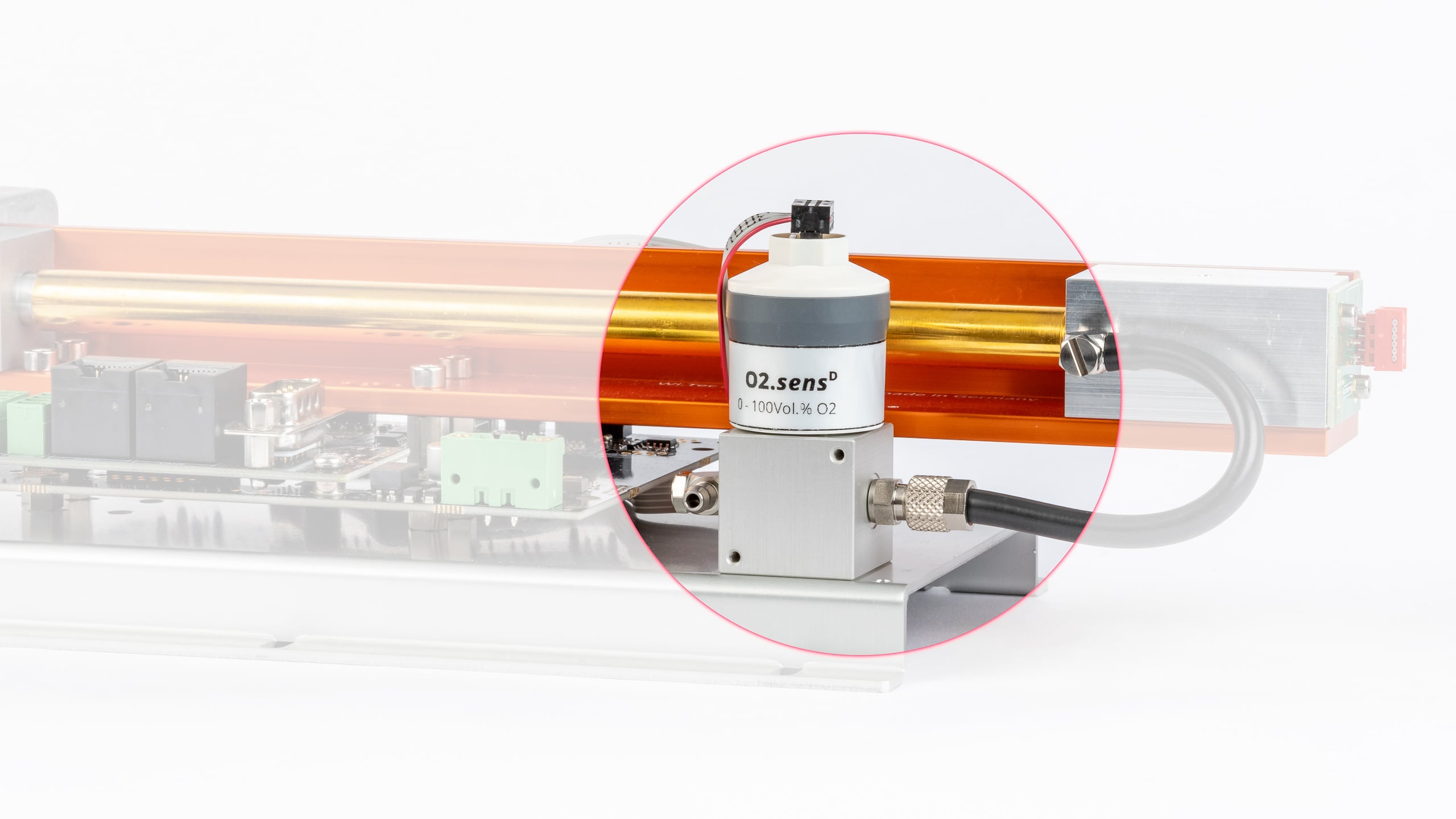
Versión Versión estándar Versión resistente a H2S Rango de medición 0 – 25 Vol.% O2 0 – 100 Vol.% O2 0,5 – 35 Vol.% O2 Solicitud Biogás, Analizador de gases de escape de automóviles Industrial, totalmente resistente al CO2 Industrial, totalmente resistente al CO2,
presenta una gran resistencia a los gases ácidosMateriales de contacto medio ABS, FKM, PPS, PTFE, acero inoxidable ABS, PVC, PPS, PTFE, acero inoxidable ABS, PVC, PPS, PTFE,
acero inoxidableVida útil prevista 1.000.000 Vol.% O2 h ~ 1.200.000 Vol.% O2 h ~ 1.200.000 Vol.% O2 h Vida útil del sensor 4 años a aire ambiente,
según la aplicación6 años a aire ambiente,
según la aplicación6 años a aire ambiente Dimensiones
(Altura x Anchura x Longitud)65,4 mm × 31,7 mm × 56,6 mm Peso 70 g Conector de tubo 4/6 mm tubo Datos de medición *
Versión Versión estándar Versión resistente a H2S Rango de medición 0 – 25 Vol.% O2 0 – 100 Vol.% O2 0,5 – 35 Vol.% O2 Resolución 0,1 Vol.% 0,1 Vol.% 0,1 Vol.% Tiempo de respuesta (t90) < 3,5 s < 10 s < 5 s Deriva ** < 1% al mes < 1% al mes < 3% al mes Error de linealidad 0 – 2 Vol.% O2: ± 0,1 abs.
2,1 – 100 Vol.% O2: ± 0,05 rel.0 – 2 Vol.% O2: ± 0,1 abs.
2,1 – 35 Vol.% O2: ± 0,05 rel.Repetibilidad *** ± 1 Vol.% O2 ± 1 Vol.% O2 Influencia de la humedad –0,03 % rel. Valor medido de O2 /
% RH–0,03 % rel. Valor medido de O2 /
% RH–0,03 % rel. Valor medido de O2 /
% RHInterferencias CO2: hasta 20 Vol.%
CO: hasta 2000 ppm
NOx: hasta 5000 ppm
HC: hasta 5000 ppm
N2O: hasta 500 ppm< 20 ppm O2 respuesta a:
100 Vol.% CO
100 Vol.% CO2
100 Vol.% C3H8
3000 ppm NO en N2
1000 ppm C6H6 en N2
500 ppm SO2 en N2
< 100 ppm O2 respuesta a:
3000 ppm C2H6O
3000 ppm C4H10S
< 200 ppm O2 respuesta a:
3000 ppm C2H6S2
< 400 ppm O2 respuesta a:
100 Vol.% H2
< 500 ppm O2 respuesta a:
2000 ppm H2S en N2< 20 ppm O2 respuesta a:
100 Vol.% CO
100 Vol.% CO2
100 Vol.% C3H8
1000 ppm C6H6 en N2
2000 ppm H2S en N2
< 20000 ppm O2 respuesta a:
3000 ppm NO en N2
1000 ppm H2 en N2
500 ppm SO2 en N2
** media de 12 meses
*** @ 100 Vol.% O2 aplicado durante 5 minParámetros de gas
Versión Versión estándar Versión resistente a H2S Rango de medición 0 – 25 Vol.% O2 0 – 100 Vol.% O2 0,5 – 35 Vol.% O2 Temperatura de funcionamiento 0 – 40 °C
intermitente 40 – 50 °C0 – 45 °C 0 – 50 °C Temperatura de almacenamiento -20 – 40 °C
5 – 25 °C recomendado
40 – 50 °C máx. 1 semana5 – 30 °C recomendado
-20 – 50 °C máximoPresión del aire 650 – 1250 hPa (mbar) 700 – 1250 hPa (mbar) 600 – 1250 hPa (mbar) Humedad ambiente 0 – 95% humedad relativa (sin condensación) Sensor de presión
Vista previa
Especificaciones
Sensor de humedad
Vista previa
Especificaciones
RITTER »MultiGas« Módulo de ajuste del punto cero (Aire)
Vista previa
Características
Especificaciones
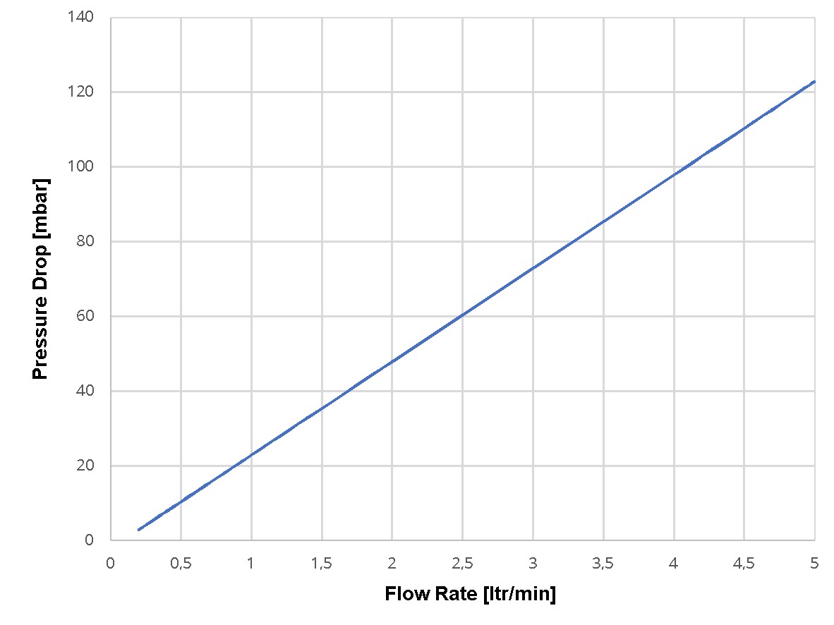
Caída de presión
Esquema del circuito
RITTER »MultiGas« Módulo de ajuste del punto cero (N2)
Vista previa
Características
Especificaciones
Caída de presión

Esquema del circuito
Salida de tensión analógica
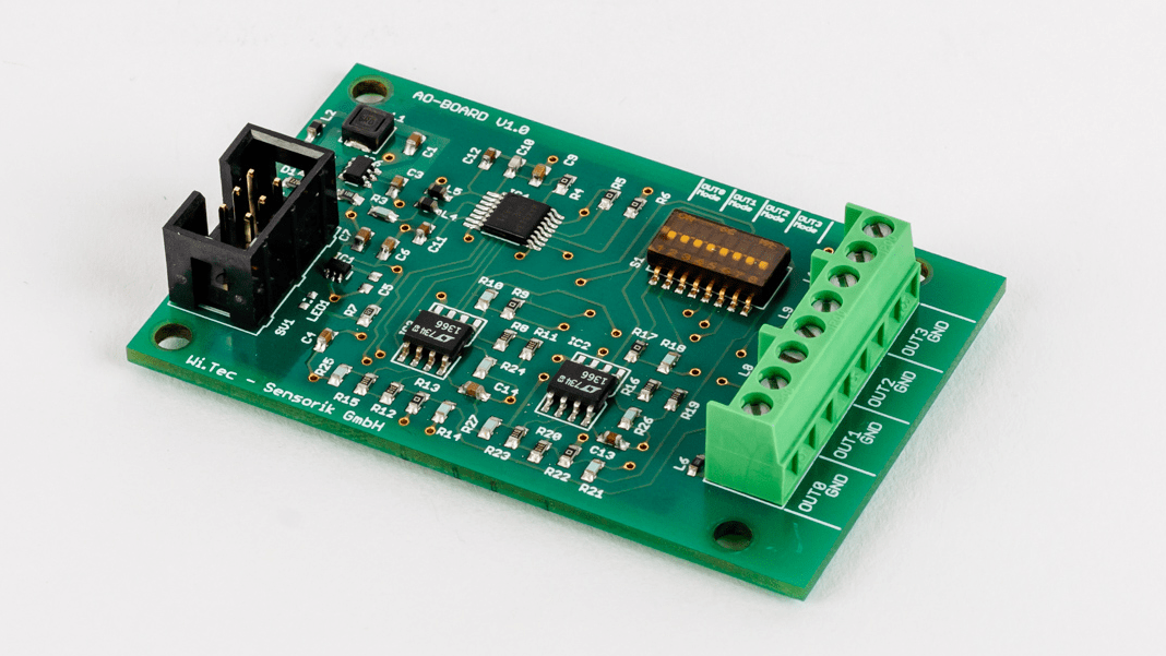
Vista previa
Datos técnicos


Número de contacto Asignación al canal Colores de los hilos del cable de conexión suministrado 1 canal 1 blanco 2 canal 2 verde 3 canal 3 amarillo 4 canal 4 gris 5 masa marrón Calentamiento y termofijación de la carcasa del sensor
Vista previa
Características
Filtro
Vista previa
Descripción
Aplicaciones
Características
Dimensiones
Especificaciones
Características Generales
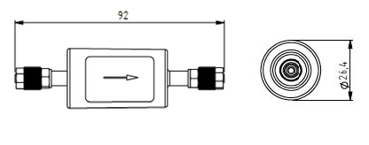
Dimensiones Ø 26,4 mm x 92 mm Peso 26 g Conector de tubo 4/6 mm tubo Caudal 0 – 4 ltr/min Solicitud Filtro de partículas Volumen de viviendas 110 ml Materiales de contacto medio Poliamida (carcasa), acero inoxidable (conector), FKM (junta tórica) Intervalo de intercambio Depende de la contaminación del gas Caída de presión (mbar) @ 1 ltr/min < 6 mbar Parámetros de gas
Temperatura de funcionamiento -5 °C – 60 °C Temperatura de almacenamiento -20 °C – 110 °C Presión máx. 8 bar Humedad ambiente 0 – 95% Humedad relativa (sin condensación) 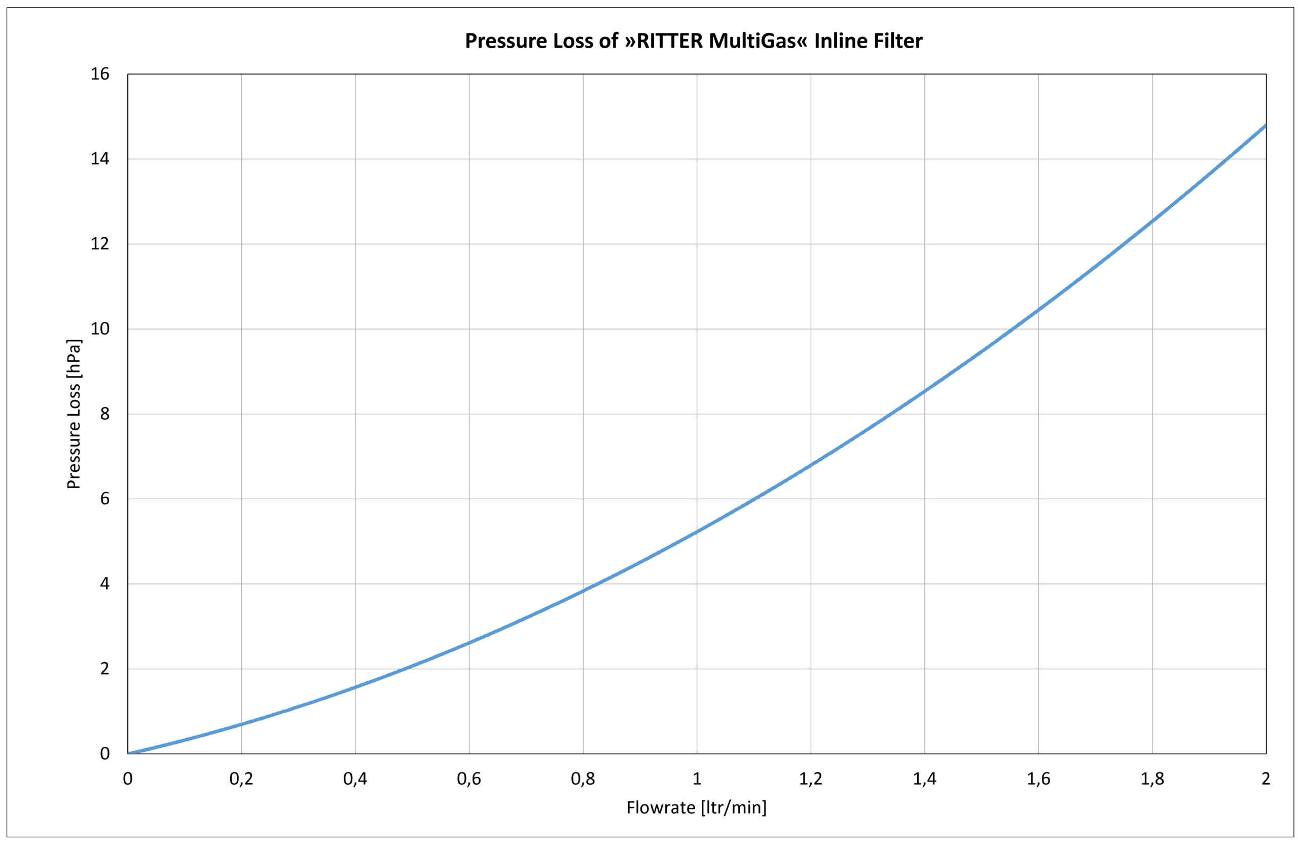
Bomba de muestreo de gas

Vista previa
Aplicaciones
Características
Dimensiones

Especificaciones
Características Generales
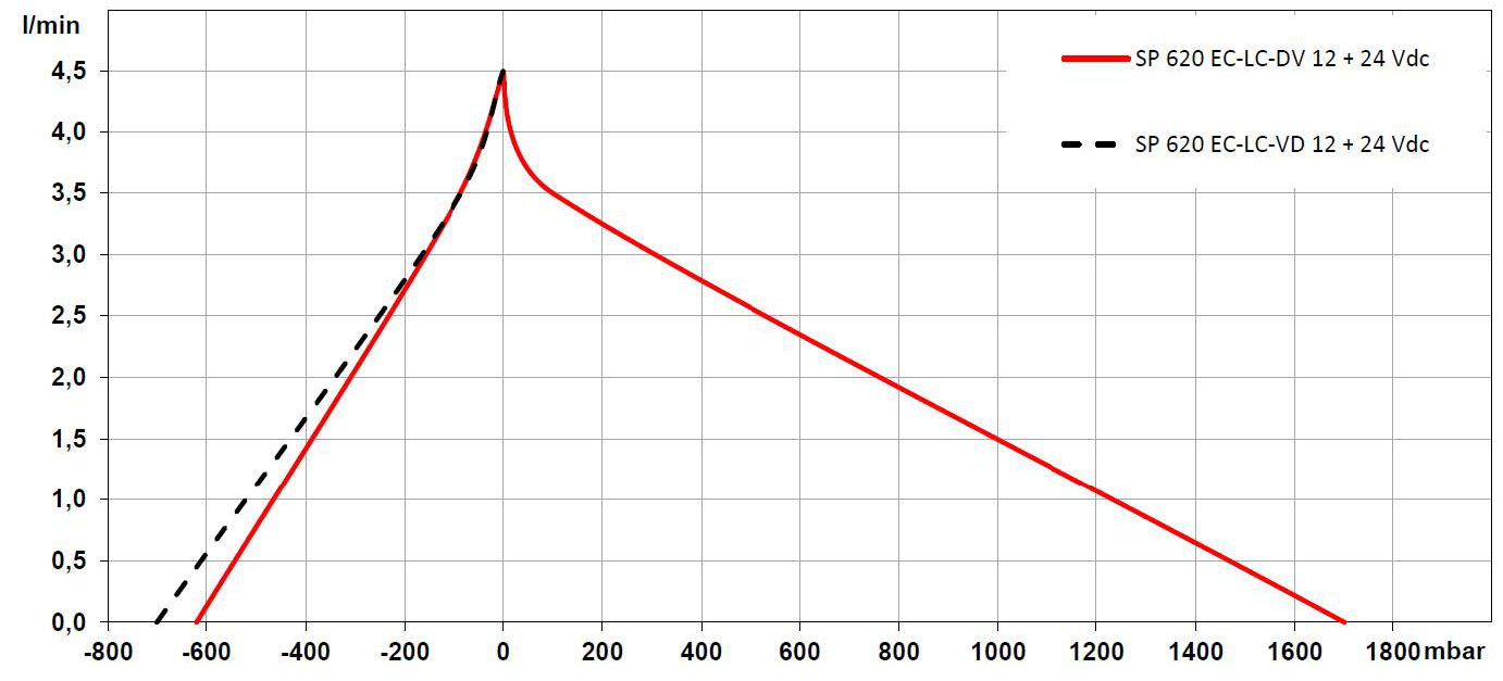
Tensión de funcionamiento 24 VDC Corriente nominal máx. 330 mA Conector neumático 4/6 mm tubo Caudal 0 – 4,5 ltr/min Presión máx. 1,7 bar Vacío máx. -620 mbar Materiales de contacto medio PVDF (altura de bombeo)
PTFE (membranas)
FFKM (válvula y junta)Peso 184 g Dimensiones A x A x L 31 mm x 54 mm x 81,5 mm Parámetros de gas
Temperatura de funcionamiento 5 °C – 50 °C Temperatura de almacenamiento -20 °C – 60 °C Humedad ambiente 0 – 95% humedad relativa (sin condensación) Diagrama de rendimiento
